Solid blue banner/background rectangle.

FOLAIDA Video Wall Processor vs Matrix: Complete Comparison Guide

FOLAIDA splicing processor, video wall controller, HDMI matrix switcher, video wall processor vs matrix, AV signal switching, command center video solution, conference room AV systemhttps://folaida.com/product-item/video-wall-processor/
Compare FOLAIDA video wall controller and HDMI matrix switcher. Learn AV signal switching differences for command center video solutions, conference room AV systems & large screen display projects.

Introduction

Splicing processors and matrix switchers are core AV signal management devices. Though both transmit audio & video signals, they vary widely in positioning, signal processing, performance and use cases. Most system integrators confuse the two during project design.
This guide breaks down key differences between FOLAIDA video wall splicing processors and AV matrix switchers, helping you pick suitable gear for video walls, conference signal scheduling, monitoring and command center builds.

1. Definition & Core Positioning

1.1 FOLAIDA Video Splicing Processor (Video Wall Controller)

Built exclusively for LCD & LED multi-screen video wall systems.

Core capability: Decode, split, scale, overlay and recombine 4K video signals for seamless multi-panel output.

Core value: Merge separate displays into one unified large screen, supporting full-screen stitching, floating window roaming, free scaling and image overlay. Widely deployed in command center large video walls.

1.2 AV Matrix Switcher

Professional signal routing and distribution hardware.

Core capability: Free cross-switching and one-to-many distribution among multi-channel inputs and outputs.

No image modification: Preserves original resolution, frame rate and picture structure.

Core value: On-demand signal sharing across multiple displays, ideal for meeting room and multimedia signal scheduling.

2. Technical & Functional Gaps

2.1 Signal Processing Power

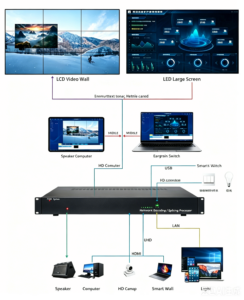
  • Splicing Processor: Advanced built-in image algorithms. Split single 4K signals for multi-panel output; supports multi-window roaming, overlay, edge blending, geometric correction, PIP/POP, 4K@60Hz & H.265 decoding for uniform wall display.
  • Matrix Switcher: Pure lossless signal forwarding only. No image stitching or window functions. Delivers stable 4K@60Hz, 18Gbps bandwidth, HDCP2.2, optional audio embed/de-embed.

2.2 I/O Layout Logic

  • Splicing Processor: Low-input, high-output design customized to video wall layouts (4 in 16 out for 4×4 / 2×8 walls). All outputs synchronized for consistent screen visuals.
  • Matrix Switcher: Balanced modular I/O (8×8 /16×16 /32×32). Any input can route to any output, perfect for multi-source multi-display signal sharing.

2.3 Control & Linkage

  • Splicing Processor: Supports scene presets, central control linkage, TCP/IP remote access for easy large wall debugging and maintenance.
  • Matrix Switcher: RS232, IR, button & TCP/IP control; features EDID management, signal preview and power-off memory for stable long-running signal switching.

3. Typical Application Scenarios

3.1 Splicing Processor Use Cases

Large integrated visualization video wall projects:
  1. Command & Monitoring Centers: Public security, traffic, power, emergency hubs for mass signal & data panoramic display
  2. Exhibition & Museum Halls: Ultra-large seamless screens with dynamic floating window effects
  3. Big Data Operation Rooms: Multi-layer data overlay for real-time visual analysis

3.2 Matrix Switcher Use Cases

Flexible multi-signal sharing scenarios:
  1. Multi-Function Conference Rooms: Switch PC, camera and video conference sources to projectors & monitors
  2. Training & Multimedia Classrooms: Unified signal distribution across multiple teaching terminals
  3. Hotel Banquet & Commercial Halls: Quick PPT, video and live signal switching for events

4. Equipment Selection Guide

Choose FOLAIDA splicing processor if your project requires seamless large screen splicing, multi-window roaming and integrated video wall visualization.

Choose HDMI AV matrix switcher if you only need flexible cross-signal switching and multi-terminal resource sharing.

Before purchase, evaluate interface compatibility, expandability and 7×24h stable operation to guarantee reliable long-term AV system performance.

Conclusion

Splicing processors focus on pixel-level image processing and seamless video wall stitching. Matrix switchers focus on lossless signal routing and flexible source distribution.

Mastering their core differences accelerates accurate equipment selection for AV integrators and project owners, improving overall system stability and visual display results.

.https://studio.youtube.com/video/2aDKrQsPr20/edit

Solid blue banner/background rectangle.

How Video Wall Processor Supports Windowing, Overlay & Roaming?

FOLAIDA splicing processor, image splitting, screen roaming, multi-screen splicing display, video wall signal processing, seamless screen switching, security monitoring video wall processorhttps://folaida.com/product-item/video-wall-processor/

Introduction

In security monitoring, conference presentation, and multimedia display scenarios, multi-screen splicing technology is widely adopted to integrate single or multiple signal sources into a large-format video wall. It supports cross-screen scaling, image overlay, free window roaming, and multi-signal synchronous display, meeting the high-standard visual management needs of commercial conferences, security scheduling, and command centers. As the core control device of the entire display system, the FOLAIDA video splicing processor relies on professional hardware decoding and independent signal processing architecture to complete real-time image splitting, restructuring, and synchronous output for multiple display units, delivering stable and flexible visual display effects for complex application scenarios.

1. Technical Principles and Core Functions of Image Processing

The FOLAIDA splicing processor acts as the core signal conversion and scheduling hub of the video wall system. Its core capabilities cover professional image splitting, multi-layer overlay, free screen roaming, and arbitrary scaling, realizing diversified dynamic display of multi-channel video signals.
Equipped with high-performance processing chips, the device supports multi-window simultaneous splitting (up to 16 windows and above). It can receive multiple independent signal sources including HDMI, VGA, DVI, and BNC at the same time. The internal professional algorithm independently divides each input signal into standard sub-images, and flexibly combines, tiles, or overlays the sub-images on the video wall according to custom setting commands.
In actual application scenarios, the powerful functions of FOLAIDA splicing processors bring great operational convenience:
  • Security Monitoring Scenarios: It supports splitting and displaying dozens of camera signals on the large screen simultaneously, realizing full-screen real-time monitoring. Users can drag any single monitoring window to an arbitrary position on the video wall through the roaming function, and perform independent scaling and focus display.
  • Conference Display Scenarios: It realizes multi-layer image overlay and picture-in-picture effects, which can synchronously display speaker video, PPT documents, data charts, and live screen signals, making conference information presentation more efficient and intuitive.

2. Hardware Composition and Core Technical Parameters

The excellent image splitting and roaming performance of FOLAIDA splicing processors is derived from mature modular hardware architecture and industrial-grade configuration. The whole device consists of four core parts: multi-type signal input ports, professional image processing chip, synchronous signal output ports, and intelligent control module, ensuring stable and efficient signal processing capabilities.
Diversified Signal Compatibility
The processor is compatible with mainstream signal interfaces such as HDMI, VGA, DVI, and BNC, and can be directly connected to monitoring cameras, office computers, video players, and professional monitoring NVR equipment without additional signal converters, realizing plug-and-play and convenient deployment.
Key Performance Parameters
  • High-frequency pixel processing: 60MHz pixel frequency, ensuring fast and accurate signal analysis and processing
  • Ultra-low response delay: 16ms ultra-fast response speed, no frame stuttering or trailing during dynamic screen switching
  • Stable signal transmission: Supports long-distance signal transmission up to 30 meters without signal attenuation
  • High-definition output resolution: Supports 1080P full HD and 4K high-definition display, restoring delicate image details
  • Industrial-grade stability: Adaptable to 15% working humidity environment, effectively preventing hardware failure and ensuring long-term stable operation

3. Intelligent Control Methods and Synchronous Operation Logic

FOLAIDA splicing processor supports dual control modes of network control and RS232 serial port control, adapting to different usage environments and intelligent integration needs, with simple operation and powerful expandability.
Network Remote Control
Users can access the device through dedicated PC software or web backend, freely setting image splitting modes, window size, arbitrary roaming position, and multi-layer overlay hierarchy. It supports one-click preset scheme saving and quick switching, which is suitable for daily conference and monitoring routine operation.
RS232 Serial Port Control
Through physical serial port connection with the central control system, it realizes hardware-level automatic linkage control, perfectly matching intelligent automated conference rooms, military command centers, and unattended monitoring scenarios.
Professional Synchronous Processing Technology
Aiming at the frame rate difference of multi-channel input signals, the built-in synchronous calibration algorithm effectively eliminates screen tearing and asynchronous phenomena. Meanwhile, the modular hot-swap design allows users to replace interface cards and upgrade hardware without shutting down the device, greatly improving later maintenance efficiency and ensuring uninterrupted system operation.

4. Core Technical Advantages and Practical Application Performance

Compared with traditional ordinary splicing devices, FOLAIDA splicing processors have obvious advantages in signal compatibility, picture quality performance, and intelligent functions, solving many pain points of traditional display systems.
Full-scene Signal Linkage Capability
Supporting 485 communication interface linkage, the device can realize intelligent linkage with external audio and video equipment, triggering automatic screen switching and window adjustment according to scenario changes, realizing automated audio and video scheduling.
Seamless Switching Technology
Adopting pre-loading image data technology, it completely eliminates black screens, stuttering, and frame loss during signal switching. Combined with 1080P high-definition resolution and 16ms ultra-low delay, it ensures smooth and coherent dynamic video display without trailing shadows.
Custom Character Overlay Function
The device supports adjustable custom text overlay, which can superimpose editable information such as time, date, location, and monitoring code on the display screen. It is widely used in security monitoring, road scheduling, and government command scenarios to facilitate accurate information recording and management.

Conclusion

FOLAIDA professional video splicing processors realize flexible and stable image splitting, arbitrary window roaming, multi-layer overlay, and seamless switching through industrial-grade FPGA hardware architecture, mature synchronous algorithm, and diversified intelligent control modes. With strong signal compatibility, ultra-low delay display performance, and convenient operation and maintenance advantages, they are widely suitable for security monitoring centers, government and enterprise conference rooms, military command centers, and multimedia exhibition scenarios. It is a high-reliability core device for building high-definition, intelligent, and efficient large-screen splicing display systems.
Company Info: Shenzhen FOLAIDA Video Technology Co., Ltd. is a professional manufacturer of video wall splicing processors, LCD splicing screens, and audio and video central control equipment, providing one-stop multi-screen splicing display solutions for global security, government, military, and commercial display fields.https://studio.youtube.com/video/2aDKrQsPr20/edit
Security operations room with numerous wall-mounted monitors showing live CCTV feeds and a desk full of laptops and control gear in use.

Navy Meeting Room Video Wall: FOLAIDA 49″ 3.5mm LG 4K + 4×8 HDMI Processor

 Navy meeting room video wall, 49 inch 3.5mm LG splicing screen, 4K military video wall, 4×8 HDMI video wall processor, movable video wall bracket, naval command room AV solutionhttps://folaida.com/product-item/video-wall-processor/

Project Overview

This is a complete military-grade audio and video upgrade project for a national navy meeting room, delivered by Shenzhen FOLAIDA Video Technology Co., Ltd. The project adopts a high-performance visual solution with 49-inch 3.5mm 4K LG splicing screens, flexible movable mounting brackets, and a 4×8 HDMI 8K video wall processor. Tailored for naval command and conference scenarios, the system realizes ultra-high-definition display, multi-signal fast switching, flexible on-site layout, and 24/7 stable operation, greatly improving the efficiency of naval command, tactical demonstration and remote video collaboration.

Project Background & Pain Points

The naval meeting room undertakes core daily tasks including real-time command scheduling, remote video conferencing, tactical intelligence display, and maritime data analysis. The original display system suffered from low resolution, large splicing gaps, signal stuttering and delayed switching, which failed to meet the navy’s strict requirements for high reliability, high definition and multi-scene emergency use.
The main technical and operational challenges are summarized as follows:
  • Ultra-high definition display demand: The site requires 8K-level visual presentation to restore complete details of tactical data, satellite imagery, maritime maps and conference documents without information loss.
  • Flexible space adaptation: The meeting room needs adjustable display layouts for different scenarios, requiring movable brackets to support rapid reconstruction of the video wall.
  • Multi-source signal processing: Multiple signal sources including computers, drone image transmission, and satellite data need smooth, fast switching and stable 24-hour continuous operation.
  • Military-grade reliability: The entire system must comply with strict naval technical standards and international maritime audio-video specifications to adapt to high-intensity military command environments.

Core Solution: 49” 3.5mm 4K LG Video Wall + 4×8 HDMI 8K Processor + Movable Bracket

FOLAIDA delivered an all-in-one military-grade visual solution: 2×2 layout 49-inch 3.5mm 4K LG splicing video wall matched with a 4×8 HDMI 8K high-definition video wall processor and customized movable mounting system. The entire system balances ultra HD display, signal stability, flexible deployment and long-term reliability for naval meeting room scenarios.

1. Display Terminal: 49-Inch 3.5mm 4K LG Splicing Screen (2×2 Layout)

Adopting original LG industrial-grade panels, the 2×2 video wall is designed for professional military and maritime visualization applications, delivering stable, high-color and high-brightness display performance.
Core Parameters
  • Original LG 49-inch industrial panel, 16:9 classic ratio
  • 1080P native resolution, supports 4K signal decoding and input
  • 3.5mm ultra-narrow physical splicing bezel
  • 520cd/m² high brightness, suitable for bright indoor conference environments
  • 178° ultra-wide viewing angle for multi-position naval staff observation
  • 10-bit color depth (1.07 billion colors) for accurate intelligence color restoration
  • 8ms fast response speed, no ghosting for dynamic tactical videos
  • 60,000-hour service life, supports 7×24-hour continuous operation
Smart Scene Adaptation: The system supports scheduled power on/off and 16 groups of customizable display presets, enabling one-click switching for daily meetings, tactical drills, report presentations and emergency command scenarios.

2. Core Control Device: 4×8 HDMI 8K Video Wall Processor

The FOLAIDA 4-in 8-out HDMI video wall processor serves as the core signal scheduling hub, supporting 8K lossless transmission and multi-window intelligent management to meet complex naval multi-signal scheduling demands.
Core Functions & Technical Advantages
  • Multi-signal concurrent access: 4-channel HDMI input and 8-channel HDMI output allow simultaneous access of computers, surveillance cameras, drone transmissions and satellite data for fast signal switching.
  • 8K ultra-high definition processing: Supports lossless 8K signal transmission, with flexible functions including window roaming, overlay, split screen and multi-screen linkage.
  • Strong electromagnetic interference resistance: Industrial chip architecture adapts to complex electromagnetic environments in naval command rooms.
  • Automatic configuration recovery: One-click preset backup and automatic data recovery after power failure ensures uninterrupted military conferences and command tasks.

3. Flexible Deployment: Custom Movable Video Wall Bracket

To solve the fixed layout limitations of traditional video walls, FOLAIDA equipped the 2×2 video wall with a customized movable bracket system for flexible and rapid scenario switching.
  • Flexible mobility: Equipped with silent universal wheels, supporting fast displacement and layout adjustment for temporary command, joint drills and multi-form meetings.
  • High safety performance: Load capacity ≥120kg with anti-tilt locking device, ensuring stable and safe operation under long-term high-intensity naval use.
  • Height adjustable design: Adaptable to sitting and standing viewing angles, improving overall conference comfort and observation efficiency.

Project Implementation Highlights

  • Military standard compliance: The whole solution strictly follows electronic conference system engineering specifications and international maritime audio-video standards, fully adapting to local naval operation habits and military reliability requirements.
  • Full-link HD transmission: From LG display panels to the 8K processor, the entire signal chain supports lossless 4K/8K HD transmission, ensuring zero image loss for tactical data and satellite intelligence.
  • Fast deployment & low maintenance: The movable bracket supports rapid installation and debugging within 30 minutes without complicated wiring. The processor supports remote centralized control and 24/7 technical support, greatly reducing operation and maintenance costs.
  • Cost-effective customized solution: Optimized configuration based on naval budget requirements, realizing military-grade stability and ultra HD display with reasonable overall project cost.

Project Achievements & Operational Value

  • Improved command efficiency: 8K ultra HD visualization and instant signal switching realize synchronous display of tactical data, conference content and real-time monitoring, accelerating naval decision-making and emergency response.
  • Multi-scene compatibility upgraded: The movable video wall structure supports flexible layout reconstruction, fully adapting to daily meetings, joint military drills and temporary emergency command missions.
  • Reduced long-term O&M costs: Industrial-grade hardware design plus remote management capability lowers manual maintenance pressure and supports 24-hour uninterrupted naval duty requirements.
  • International standard upgrade: Adopting LG international premium panels and industrial 8K processors, the system meets global maritime AV standards and promotes the informatization and internationalization of naval command construction.

Core Parameter Overview

Device Type
Core Parameters
Project Advantages
LG Splicing Screen
49-inch, 3.5mm bezel, 4K input, 520cd/m² brightness
Ultra-narrow gap, high-definition display, 7×24-hour stable operation
Video Wall Processor
4×8 HDMI port, 8K lossless transmission
Multi-signal fast switching, preset backup, strong anti-interference
Movable Bracket
Load ≥120kg, silent casters, height adjustable
Fast deployment, flexible scene adaptation, military-grade safety
Applicable Scenarios
Naval meetings, command scheduling, tactical drills
Full-scene coverage, high stability, military standard

Conclusion

This naval meeting room upgrade project fully demonstrates FOLAIDA’s professional strength in military and marine audio-video visualization solutions. The combination of LG industrial splicing screens and high-end 4×8 HDMI 8K processors delivers ultra-stable, high-definition and flexible display performance, effectively empowering modern naval informatization construction. Shenzhen FOLAIDA Video Technology Co., Ltd. continues to provide reliable commercial and military-grade video wall solutions for global government, military, marine and security command centers.
Company: Shenzhen FOLAIDA Video Technology Co., Ltd. — Professional manufacturer of LG splicing screens, military video wall systems, HDMI video wall processors and movable display bracket solutions.https://studio.youtube.com/video/2aDKrQsPr20/edit
Conference room with several ergonomic chairs around a long table; a wall of large video screens displays the Defensoría del Pueblo Colombia logo and microphones on the desk.

FOLAIDA Solution: 55 Video Wall & Splicing Processor

[layerslider id=”7″]
FOLAIDA 24×24 HDMI splicing processor & 55″ 1.8mm LG 4K video wall upgraded Latin America DAS command center, delivering seamless display and stable signal scheduling for security scenarios.https://folaida.com/product-item/video-wall-processor/

Project Overview

Latin America’s core national security agency DAS adopted FOLAIDA turnkey visualization solution to upgrade its command center. The system uses 3×7 layout 55-inch 1.8mm ultra-narrow bezel LG 4K video wall and 24×24 HDMI video splicing processor. It achieves seamless HD display, multi-signal sync scheduling and fast emergency response, now a regional benchmark for command center renovation.

1. Project Background

DAS undertakes intelligence, anti-terrorism, border security and judicial investigation tasks. Its command center needs round-the-clock access to massive surveillance videos, geographic data and conference signals.
The old system had obvious flaws: large splicing gaps, low resolution, signal lag and poor compatibility, which dragged down command efficiency and emergency disposal speed. After strict selection, DAS chose FOLAIDA industrial-grade splicing solution for full system upgrade.

2. Core Solution

2.1 55-inch 1.8mm 4K LG Video Wall (3×7 Layout)

Equipped with original LG industrial panels, the video wall features 1.8mm ultra-narrow bezel, 4K resolution and high brightness. It supports 7×24 continuous operation, delivers seamless visual effect, accurate color restoration and excellent anti-interference performance, perfectly presenting monitoring details and data.

2.2 24×24 HDMI Splicing Processor

Adopting pure FPGA hardware architecture, this 24-in 24-out processor supports full 4K@60Hz signals with delay below 5ms. It enables screen roaming, picture-in-picture, window overlay and one-click scene switch. With N+1 redundant power supply and hot-swap design, it runs stably 24/7 and is highly compatible with mainstream security and conference devices.

3. One-Stop Service

FOLAIDA provides full-process services including on-site survey, customized design, standard installation, gap & color calibration, system debugging, on-site training and after-delivery support. All work is implemented strictly to meet high standards of national security projects.

4. Project Outcomes

  • Realizes full coverage of multi-region security monitoring with clear 4K visuals.
  • Efficient multi-signal scheduling lifts command efficiency by over 60%.
  • Stable 24/7 operation ensures uninterrupted security work.
  • Emergency response time is shortened by more than 50%.
  • The project becomes a well-recognized benchmark case across Latin America.

5. About FOLAIDA

Shenzhen FOLAIDA Video Technology specializes in industrial video walls and splicing processors. We supply original LG/Samsung panels with multiple sizes and bezel options, and deliver customized turnkey solutions for command centers, security monitoring and government projects worldwide.
We own rich global project experience and offer 24-hour technical support plus lifelong maintenance, ensuring reliable long-term operation for all systems.

Conclusion

This DAS project fully proves the outstanding performance and reliability of FOLAIDA video walls and splicing processors. We keep optimizing high-definition, high-stability visualization solutions to serve global security, government and smart monitoring industries.

.https://studio.youtube.com/video/2aDKrQsPr20/edit

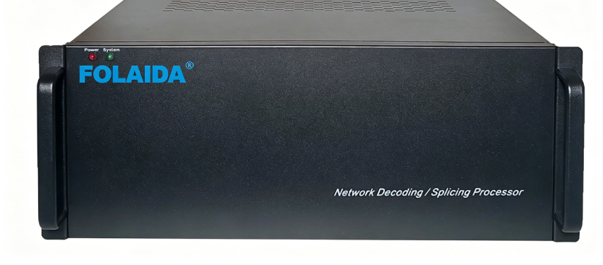
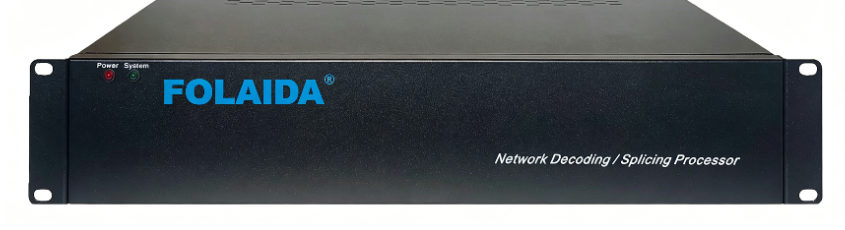
Front view of a rack-mount network decoding/splicing processor labeled FOLAIDA, with Power and System LEDs on the left.

FOLAIDA Video Splicing Processor: Definition, Core Functions & Technical Advantages

What Is a Video Splicing Processor?

A video splicing processor is a professional high-performance video processing and control core device specially designed for large-screen display systems. It serves as the central control hub for multi-screen splicing display solutions. The core working principle of the device is to split a complete ultra-high-definition video image signal into multiple independent image blocks, then accurately distribute the divided image signals to each independent video display unit such as projection units and splicing screens. Through this professional processing method, multiple ordinary display units can be combined into a seamless, ultra-large dynamic splicing display wall, realizing ultra-wide and super-large screen image presentation that a single display device cannot achieve. In addition, the video splicing processor supports the simultaneous access and synchronous processing of multiple types of video equipment and signal sources, with strong signal compatibility and multi-channel expansion capabilities.https://folaida.com/product-item/video-wall-processor/

Core Functions of Video Splicing Processor

1. Automatic Image Parameter Calibration

The device is equipped with an intelligent automatic adjustment system for image parameters, which can precisely and smoothly optimize the brightness, contrast, and chroma of the displayed images in real time. It effectively eliminates image distortion, color deviation and blurry problems caused by long-term operation or different display unit parameters, ensuring stable and uniform display effects for the entire splicing screen wall at all times.

2. Multi-Mode Edge Processing Technology

To adapt to different display scenarios, screen specifications and splicing requirements, the processor integrates three professional edge processing technologies. It can freely switch and match processing modes according to on-site use conditions, effectively eliminating splicing gaps, edge flickering and image dislocation, and achieving flawless, ultra-smooth seamless splicing visual effects.

3. Digital Multi-Screen Color Balance Technology

Built with an exclusive digital multi-screen color balance module and professional digital three-primary color adjustment circuit, the video splicing processor can suppress the discrete color difference of red, green and blue primary colors between different projection and display units. It realizes the unified calibration of three-primary color parameters for all splicing units, completely solving the common problem of inconsistent color display of traditional splicing screen walls. The overall display screen presents highly consistent color performance without obvious color difference and layering.

4. Pure Hardware FPGA Architecture for Stable Operation

Adopting large-scale array FPGA pure hardware architecture, the processor operates independently without relying on any operating system or hard disk. The hardware-based working mode realizes truly maintenance-free operation, completely avoiding common failures of traditional software equipment such as system crash, hardware resource conflict, network virus intrusion and program stuttering. It supports 7×24 hours of continuous stable operation, which is highly suitable for commercial display, monitoring scheduling and other long-term working scenarios.

5. High-Definition Color Sampling & Display Performance

The device supports up to 4:4:4 full-color sampling, which can restore rich and delicate image colors without color loss and compression. It perfectly outputs 1080P full high-definition display quality, restores real and vivid picture details, and greatly improves the overall display resolution and visual layering of the large splicing screen.

6. Pure Digital Synchronization Technology for Dynamic Video

Equipped with single-clock pure digital synchronization technology, the processor realizes microsecond-level synchronous output of multi-screen images. When playing high-speed dynamic videos such as live events, monitoring videos and dynamic advertising screens, it ensures seamless and smooth connection of each screen image, eliminates frame skipping, stuttering and picture asynchrony, and presents high-quality dynamic visual effects.

Overview & Application Value

In short, the core value of the video splicing processor is to realize intelligent image segmentation, synchronous distribution and seamless splicing. It supports multi-channel video signal simultaneous access and split-screen display, enabling multiple video signals to be displayed synchronously and independently on one ultra-large splicing screen wall. As an indispensable core device of large-screen display systems, it is widely used in command centers, security monitoring, commercial advertising, exhibition display, stage performance and other scenarios, providing stable, high-definition and seamless professional display solutions for various large-screen splicing projects.https://studio.youtube.com/video/2aDKrQsPr20/edit
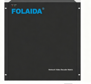
Front view of a FOLAIDA Network Video Decoder Matrix, a black rack-mount device with blue logo on the front panel and side handles.

HDMI Matrix vs Network decoding processor

[layerslider id=”7″]

Compare HDMI matrix switcher and network decoding processor. Learn their signal processing differences, functions & applicable scenarios for conference AV systems, monitoring rooms and large video wall projects.https://folaida.com/product-item/video-wall-processor/
No. Comparison Parameter HDMI Matrix Network Decoding Processor
1 Wiring Method HDMI input and HDMI output (NVR connects to HDMI input; HDMI output connects to the large display) Network cable input to switch (one network cable connects to the switch; HDMI output connects to the large display)
2 Single Screen Display One image per screen; only one input source can be displayed on a single screen Multiple images per screen; supports screen splitting (1/4/6/8/9/10/16/25/30 views)
3 Control Options Front Panel / Remote Control / RS232 RS232, RS485, PC software, APP control, WEB control
4 Switching Time 1 second Near-zero latency
5 Video Wall Function Not built-in; requires supporting video wall software for splicing Built-in video wall splicing function
6 Advanced Functions None Supports windowing, overlay, roaming, and zoom functions
7 Decoding Capability None Supports multi-brand, multi-resolution IP cameras via standard protocols such as ONVIF, RTSP, and RTMP
8 Playback Function None Supports video playback from Hikvision and Dahua DVRs/NVRs
9 OSD Text Overlay None Supported
10 LED Text Function None Supported

KVM Extenders: FAQs

In this FAQ, you will find answers to some basic questions about KVM extenders. Read on to learn about what they are, how they work, where they are used, their benefits, the maximum distance that signals can be extended, and more.https://folaida.com/product-item/video-wall-processor/

What is a KVM extender? What does a KVM extender do?

A keyboard, video, and mouse (KVM) extender enables users to work on a computer from a distance. Typically, it is a set of transmitter and receiver appliances. The KVM transmitter unit is connected to the computer system and captures the peripheral signals such as universal serial bus (USB) for keyboard and mouse, audio, and video. These signals are extended to a remote user station where the monitors, keyboard, and mouse are powered by the KVM receiver unit. KVM extenders overcome the distance limitation of HDMI®, DisplayPort™, and USB cables and transport these signals anywhere from 15 feet to several miles away from the system.

How does a KVM extender work?

KVM extenders consist of a transmitter and receiver pair. A transmitter unit is located next to the computer system, and a receiver unit resides at the remote user station. The units communicate with each other over copper (such as CAT5e) or fiber optic cabling.
The KVM transmitter unit captures the input/output (I/O) signals from the computer—while the most common signals are video, audio, and USB for control, some models also extend RS232 and infrared (IR) signals. The KVM extender encodes these signals and uses either proprietary or standard internet protocol to transport them to the KVM receiver unit, which decodes these signals and powers the remote peripheral devices (such as displays, keyboard, mouse, and speakers).

What are the benefits of using KVM extenders?

A KVM extender is useful wherever there is a need to control a computer from a distance—which could be for a variety of purposes. The most common reasons to use a KVM extender include user comfort and safety, centralization of equipment for security and easy maintenance, and enabling/improving collaborative efforts. When a user needs to work on more than one system, using KVM extension with switching solutions declutters and optimizes desk space—since multiple computers can be controlled with a single set of displays, keyboard, and mouse.

Where are KVM extenders used?

KVM solutions are deployed in a wide range of industries and control room applications to improve security, ergonomics, and collaboration—from industrial control rooms to military and defense command centers, airport management, transportation, emergency dispatch centers, post-production, broadcast, education and healthcare, to name but a few.

What are IP KVM extenders?

IP KVM extenders enable users to work on a computer from a distance. They use internet protocol to transmit signals from point A to point B, convert the signals into packets, and distribute them through standard commercial off-the-shelf (COTS) network switches. IP KVM extenders offer many advantages over point-to-point KVM extenders. They enable the design of KVM matrix systems over IP, where any source system can be accessed from any remote location on the network. The network switch effectively replaces the traditional KVM matrix switch and provides better scalability.

What is a KVM switch? How is it different from a KVM extender?

KVM switch is a hardware device that allows a single user to control multiple computers with a single set of displays, keyboard, and mouse attached to the KVM switch. The primary goal of the KVM extender on the other hand is to extend the video, keyboard, mouse, audio, and USB signals of the system to a remote user station. IP KVM extenders support both of these functions—they extend the KVM signals over IP and allow users to control multiple computers from a single set of displays, keyboard, and mouse attached to the KVM receiver unit. With IP KVM extenders, the network switch effectively replaces the fixed-port KVM switch.

What cable types are supported for transmission?

Typically, two types of KVM extenders can be found—those that support fiber optic cabling, and others that support CATx (copper wire) cabling. Some KVM extenders can support both types of cabling. The type of cabling required will be dictated by the distance the signals need to be extended (fiber optic cables support the longest distance), the environmental conditions, and the security level required (fibre optic cable is immune to electro-magnetic interface and considered more secure).

What is the maximum distance that the signals can be extended?

This depends largely on the cabling and the design of the KVM extender. As a general guideline, CATx cables support a maximum distance of about 100 meters (328.08 feet) in point-to-point extension, while IP KVM extenders support longer distances over CATx networks. Fiber optic cables provide a quantum jump in distance supported than CATx—for example, fiber optic single-mode cabling can cover up to 10 kilometers (6.21 miles).

What are the common video connection standards?

DisplayPort and HDMI are the most common video connection standards available on modern graphics cards and displays. The HDMI and DisplayPort specifications establish the maximum supported resolution per revision, the required bandwidth, and the corresponding high-bandwidth digital content protection (HDCP) revision.

What is HDCP?

HDCP is a hardware encryption specification that protects digital content from being transmitted to non-compliant devices and prevents the unauthorized duplication of the content.

How many monitors can I extend with a KVM extender?

Select high-performance KVM extender models support multi-display configurations, extending up to four video signals with a single transmitter/receiver pair over a single fiber-optic or CATx cable. To support higher number of displays, multiple KVM extenders can be used with a system.

Why does bitrate matter in IP KVM installations?

Bitrate measures the amount of data transmitted per second, generally in megabits per second (Mbps). It indicates the amount of bandwidth an IP KVM extender requires for transporting audio, video, and USB signals over the network. Evaluating the available network bandwidth is critical in planning and deploying an IP KVM solution.

What type of security features do IP KVM extenders support?

IP KVM extenders could offer several security features, such as encryption to protect the confidentiality of the information transmitted, and user authentication to prevent unauthorized remote access to systems.

Can a user access multiple computers with IP KVM extenders?

Yes. Select IP KVM extender models support many-to-one configurations. A user can control multiple systems from a single receiver unit (remote user station).

Can multiple users access the same computer with IP KVM extenders?

Yes, select IP KVM extender models support one-to-many configurations. Multiple users can access the same computer system from different receiver units (different remote user stations).

Can I switch between two computers running different operating systems (for example, Windows® and Linux®)?

Yes, select IP KVM extenders are compatible with multiple operating systems, and they allow switching between two computers each running a different operating system. A user can then work remotely on these computers from a single receiver unit that powers single set of displays, keyboard, and mouse.

What is the SRT Protocol?

Understanding The Secure Reliable Transport Protocol

SRT (Secure Reliable Transport) is a royalty-free, open-source video streaming transport protocol that delivers secure low-latency streaming performance over noisy or unpredictable (lossy) networks such as the public internet. SRT uses an intelligent packet retransmit mechanism called ARQ (Automatic Repeat reQuest) on top of a UDP data flow to protect against packet loss and fluctuating bandwidth, as well as to ensure the quality of your live video.

High-quality, low-latency live videos

The use of video in businesses, governments, schools, and defense is on a sharp rise. Many protocols have addressed compatibility distribution of streaming video to very large volume of viewers consuming content from disparate devices and appliances. However, one of the best ways to leverage the assets already on premises at various organizations, as well as the considerable investment by service providers in the cloud, is to feed streaming distribution tools with very low-latency video and do so reliably.

SRT takes some of the best aspects of User Datagram Protocol (UDP), such as low latency, but adds error-checking to match the reliability of Transmission Control Protocol/Internet Protocol (TCP/IP). While TCP/IP handles all data profiles and is optimal for its job, SRT can address high-performance video specifically.

What are the common applications of SRT?

IT thought leaders among enterprise and government end-users are especially excited about SRT because it’s a viable replacement for the Real-Time Messaging Protocol (RTMP). RTMP is a TCP-based streaming protocol originally developed to work with Adobe Flash players and still in use today as a protocol for live streaming video.

RTMP’s primary function is to deliver content from an encoder to an online video host. Known for its low-latency streaming and minimal buffering capabilities, RTMP was often used by broadcasters for streaming live events in real time. However, because RTMP cannot stream HEVC video content, it’s not ideal for new applications. SRT, unlike RTMP, is codec agnostic and can stream any type of video content.

What are the benefits of using the SRT protocol?

Streaming video over the internet can be a challenge due to unpredictable network conditions, including unstable connections, bandwidth limitations, and latency issues. SRT supports:

  • Pristine quality video – SRT is designed to protect against jitter, packet loss, and bandwidth fluctuations due to congestion over noisy networks for the best viewing experience possible. This is done through advanced low latency retransmission techniques that compensate for and manage the packet loss. SRT can withstand up to 10% packet loss with no visual degradation to the stream.
  • Low latency – In spite of dealing with network challenges, video and audio is delivered with low latency. It has the combined advantages of the reliability of TCP/IP delivery and the speed of UDP.
  • Secure end-to-end transmission – Industry-standard AES 128/256-bit encryption ensures protection of content over the internet. SRT provides simplified firewall traversal.
  • Leveraging the internet – Because SRT ensures security and reliability, the public internet is now viable for an expanded range of streaming applications—like streaming to cloud sites (for example, LiveScale omnicast multi-cloud platform’s concurrent distribution to multiple social media such as Facebook Live, YouTube, Twitch, and Periscope from one live video feed), streaming or remoting an entire video wall content, or regions of interest of a video wall, and more.
  • Interoperability – Users can confidently deploy SRT through their entire video and audio streaming workflows knowing that multi-vendor products will work together seamlessly.
  • Open source – Royalty-free, next-generation open-source protocol leads to cost-effective, interoperable, and future-proofed solutions.

What are the common applications of SRT?

SRT also addresses security concerns and focuses on performance video – even through public internet infrastructure. Common applications of SRT include:

  • Remote broadcasting
  • Online video platforms
  • Content delivery networks
  • Enterprise video content management systems
  • Hardware, software, and services internet streaming infrastructure companies

What is the SRT Alliance?

Established in 2017, the SRT Alliance is a community of industry leaders and developers that aims to support the free availability and collaborative development of the SRT protocol.

Matrox Video is a member of the SRT Alliance and endorses the use of SRT.

Introduction to Color Spaces in Video

What is color space?

Color space is a mathematical representation of a range of colors. When referring to video, many people use the term “color space” when actually referring to the “color model.” Some common color models include RGB, YUV 4:4:4, YUV 4:2:2, and YUV 4:2:0. This page aims to explain the representation of color in a video setting while outlining the differences between common color models.

How are colors represented digitally?

Virtually all displays—whether TV, smartphone, monitor, or otherwise—start by displaying colors at the same level: the pixel. The pixel is a small component capable of displaying any single color at a time. Pixels are like tiles on a mosaic, with each pixel represents a single sample of a larger image. When properly aligned and illuminated, they can collectively be presented as a complex image to a viewer.

While the human eye perceives each pixel as a single color, every pixel is actually made up of the combination of three subpixels colored red, green, and blue.

Pixel representation of a sample of a larger image

While the human eye perceives each pixel as a single color, every pixel is actually made up of the combination of three subpixels colored red, green, and blue.

By combining these subpixels in different ratios, different colors can be obtained.

                                                         RGB color space

By mixing red, green, and blue, it’s possible to obtain a wide spectrum of colors. This is referred to as RGB additive mixing.

The color space itself is a mathematical representation of a range of colors:

8-bit vs 10-bit color

8-bit and 10-bit refer to the number of bits per color component or color depth.
RGB 8 bits (sometimes written as RGB 8:8:8) refers to a pixel with 8 bits of red component, 8 bits of green component, and 8 bits of blue component. This means that each color component can be represented in 28, or 256 hues. Since there are three color components per pixel, this leaves a total of 2563, or 16.77 million possible colors per pixel.
Similarly, RGB 10 bits refers to a pixel with 10 bits of red component, 10 bits of green component, and 10 bits of blue component. Each color can therefore be represented in 210, or 1024 hues, leaving a total of 10243 or 1.074 billion total possible pixel colors.

                                                      YUV or YCbCr color space

YUV color space was invented as a broadcast solution to send color information through channels built for monochrome signals. Color is incorporated to a monochrome signal by combining the monochrome signal (also called brightness, luminance, or luma, and represented by the Y symbol), with two chrominance signals (also called chroma and represented by UV or CbCr symbols). This allows for full color definition and image quality on the receiving end of the transmission.

Storing or transferring video over IP can be taxing on network infrastructure. Chroma subsampling is a way to represent this video at a fraction of the original bandwidth, therefore reducing the strain on the network. This takes advantage of the human eye’s sensitivity to brightness as opposed to color. By reducing the detail required in the color information, video can be transferred at a lower bitrate in a way that’s barely noticeable to the viewers.

YUV 4:4:4


Full color depth is usually referred to as 4:4:4. The first number indicates that there are four pixels across, the second indicates that there are four unique colors, and the third indicates that there are four changes in color for the second row. These numbers are unrelated to the size of individual pixels.

Each pixel then receives three signals, one luma (brightness) component represented by Y, and two color difference components known as chroma represented by Cr (U) and Cb (V).

YUV subsampling

Subsampling is a way of sharing color across multiple pixels and using the eye and brain’s natural tendency to mix neighboring pixels. Subsampling reduces the color resolution by sampling chroma information at lower rate than luma information.


YUV 4:2:2 vs. 4:2:0

4:2:2 subsampling implies that the chroma components are only sampled at half the frequency of the luma:
                                                                                                 

The chroma components from pixels one, three, five, and seven will be shared with pixels two, four, six, and eight respectively. This reduces the overall image bandwidth by 33%.

Similarly, in 4:2:0 sub-sampling, the chroma components are sampled at a fourth of the frequency of the luma.

The components are shared by four pixels in a square pattern, which reduces the overall image bandwidth by 50%.
Several other chroma subsampling methods exist, but these are the two principles of chroma subsampling reducing the image bandwidth by reducing the pixel color sampling frequency remains the same.
The image below details how a 4×2 pixel region is represented in 4:2:0 and 4:2:2 subsampling.
                                                                                                   
In the example below, the three frames (one luminosity and two chromas) can be combined to create the final colored image:
                                                                                                     

Monochrome

Since most displays are black by default, the simplest way to portray an image is by brightness only. This is known as a monochromatic image:

In such cases, the incoming signal will only have a luma (Y) component, and no chroma components (U or V).


Subsampling size saving

With 8 bits per component,

  • In 4:4:4, each pixel will require three bytes of data (since all three components are sent per pixel).
  • In 4:2:2, every two pixels will have four bytes of data. This gives an average1 of two bytes per pixel (33% bandwidth reduction).
  • In 4:2:0, every four pixels will have six bytes of data. This gives an average of 1.5 bytes per pixel (50% bandwidth reduction).


When to use chroma subsampling and when to avoid?

Chroma subsampling is a useful method to use for natural content, where lower chroma resolution isn’t noticeable.
On the other hand, for complex and precise synthetic content (for example, CGI content), full color depth is needed to prevent visible artifacts (edge blurring), since the pixel precise content may exacerbate them.
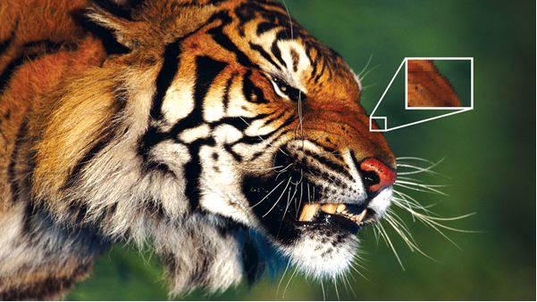
The images below show how CGI data can be impacted by subsampling.

                                                                                                                               Chroma sub-sampling 4:4:4 vs 4:2:2 vs 4:2:0
The finer details are lost when this image is displayed using chroma subsampling. This can be dangerous in mission-critical environments where key decisions are made based on the presented data. When sampling text at 4:2:2 or 4:2:0, then the quality will drop making said text increasingly difficult to read.
When choosing products for video walls, for example, it’s crucial to choose technologies that allow versatility with regards to color space. Take a control room for instance. Part of the control room wall may display charts or graphs where every detail matters. In this case, a capture, encoding, decoding, and display product which has the capability to handle 4:4:4 is better suited. On the other hand, if watching a feed of high motion content, say a sports event, then the overall network bandwidth could be reduced by having this video play at 4:2:0. Versatility is key when choosing products for capture, streaming, recording, decoding, and display as it allows the user to reach a wider range of functionality.


Is YUV 4:4:4 the same as RGB?
While the output image will look very similar, and the bandwidth required to transfer the image will be the same2, the storage and transfer of data will differ between the two.
RGB will transmit content with a predetermined color depth per component. This means that each of the R, G, and B will contain data for each of the red, green, and blue color components respectively to collectively formulate the overall color of each pixel.
YUV, on the other hand, will transmit each pixel with the associated luma component, and two chroma components.

                                                               Color space conversion

It’s possible to convert between RGB and YUV. Converting to YUV and using subsampling when appropriate will help reduce the bandwidth required for this transmission.

Videowall Processor Features

Dedicated Video Bus

Centralized videowall processors use a data bus to transport video from their inputs to their outputs. Some systems incorporate a dedicated bus for this purpose, while other systems use a common bus for transferring video as well as other inter-system communication. Use of a dedicated video bus ensures that the transfer of video data is not impeded by other activity, providing more reliable, stutter-free video playback, and ensuring the processor responds to user commands in real-time.https://folaida.com/product-item/video-wall-processor/

Scalability

Some end users will want to add more input or output channels over time. This may be part of a phased installation, or an unforeseen upgrade. While some processors are easily expandable, some have a “fixed configuration,” and cannot be changed after leaving the factory. Other videowall processors are upgradeable, but may require on-site support from their manufacturers to make hardware configuration changes. For a distributed videowall processing system, or a centralized videowall processor that accepts sources streamed over a network, potentially up to hundreds of input sources may be supported.

Redundancy & Accessibility Features

For videowall processors used in missioncritical or 24/7 environments, redundant and hot-swappable components are essential. Redundant, hot-swappable power supplies keep processors running during a failure, and facilitate replacement without powering down the unit. Hot-swappable fans can quickly and easily be replaced if necessary. The ability to replace these components, without removing the videowall processor from the rack will minimize downtime.

Upscaling and Downscaling Quality

Maintaining image quality is crucial for videowall processors, which often display large images at high resolution, or downsize images into smaller windows or “thumbnails.” Depending on the quality of the image processing, scaling sources up or down from native resolution can compromise image integrity. Poor scaling can produce artifacts, which can make imagery ineffective for applications requiring critical analysis of images.

Accurate Input Detection

Incoming source signals can vary widely in signal format and resolution. Quick, accurate input detection and configuration of input sources is ideal. Slow auto-detection can produce blank windows that are presented for an undesirable length of time when switching between window layouts or input sources. Inaccurate input signal detection can result in images shifted horizontally or vertically, displayed at the wrong aspect ratio, or presented with other visual distortions and artifacts. Manual programming to correct these issues for each input can add weeks of programming that could have otherwise been avoided if quick and accurate input detection was supported. This capability also makes integration of new sources, or temporary sources such as guest laptops, simple and easy.

HDCP Support

High-bandwidth Digital Content Protection, or HDCP, is an encryption system widely used for content delivered by Blu-ray Disc players, satellite and cable TV receivers, and PCs. To properly display digital encrypted content, all devices in the signal chain must be HDCP-compliant. The increasing use of digital video sources has made HDCP compliance a growing requirement for videowall processors.

Multiple Output Resolutions

Some videowall processors can output multiple signal formats simultaneously. This is useful for systems that incorporate displays of various resolutions, such as a videowall comprised of large 1920×1080 projection cubes flanked by 1366×768 flat panels as auxiliary displays. However, processors limited to one output format should feed a signal at the native resolution of the videowall displays. For auxiliary displays, signals from the processor may be upscaled or downscaled to match their native resolutions.

Window Borders, Titles, and Clocks

A videowall processor’s ability to add colored borders and text to source windows can be a powerful feature in many applications. Colored borders can denote the status of the content in a command and control room, such as green for unclassified data and orange for top secret data. In a traffic monitoring environment, a red border can help highlight an accident, or colors can be used to indicate traffic levels. Overlay text can be used to provide information about the source, such as the location of a reporter, and the local time. Clocks displaying the time for different regions or time zones can be generated by many processors, allowing an integrator to streamline system designs by avoiding the need for external clocks or status displays.

Remote Control Protocol

Some applications may require a touchpanel controller, or use of a customized application for videowall control. In these systems, the videowall processor must support Ethernet or RS-232 remote control. The range of control options will vary from manufacturer to manufacturer, so it is important to make certain that all required control capabilities are supported. This topic is covered in detail in Videowall Processor Control.

Application Control

Videowalls in data-driven environments such as utilities and network centers often require the ability to manage applications presented on the videowall using a keyboard and mouse. This can be accommodated by installing and operating applications directly on some videowall processors, much like a PC. Other solutions integrate hardware or networked software switching systems to manage keyboard and mouse control directly on the source machines. Software solutions require compliance with operating systems and network security requirements, while hardware solutions require more cabling and control integration.

Preview Output

Some organizations require that a smaller presentation of the videowall be viewed elsewhere in a facility, on one or two screens, or be streamed to another location. This allows other staff to see an overview of the videowall, without requiring use of a large number of display devices. Some processors provide a preview output of the videowall within the control software, or automatically generate an output that can be connected to a display. Other processors allow preview layouts to be programmed and presented on additional outputs. This method requires that the videowall processor supports presentation of a single input on different displays and different window sizes, a feature not supported by all processors.https://studio.youtube.com/video/2aDKrQsPr20/edit

Related Links


  • Video Wall Processor– Explore advanced video wall processor options designed for seamless HD display control and management.
  • LCD Video Wall Solution– Discover comprehensive LCD video wall solutions that complement high-resolution processor technology.
  • HDBaseT Matrix Switcher– Learn about HDBaseT matrix switchers that enhance signal distribution for large venue displays.
  • Certificates– Verify compliance and safety standards with certified video wall processor products.
  • FAQ– Find answers to common questions about video wall processors and related digital signage technology.