Video wall processor solution components for multi screen display systems
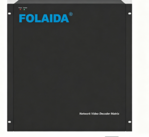
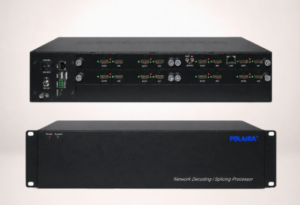
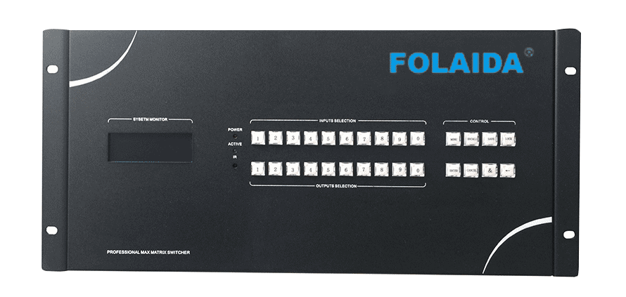
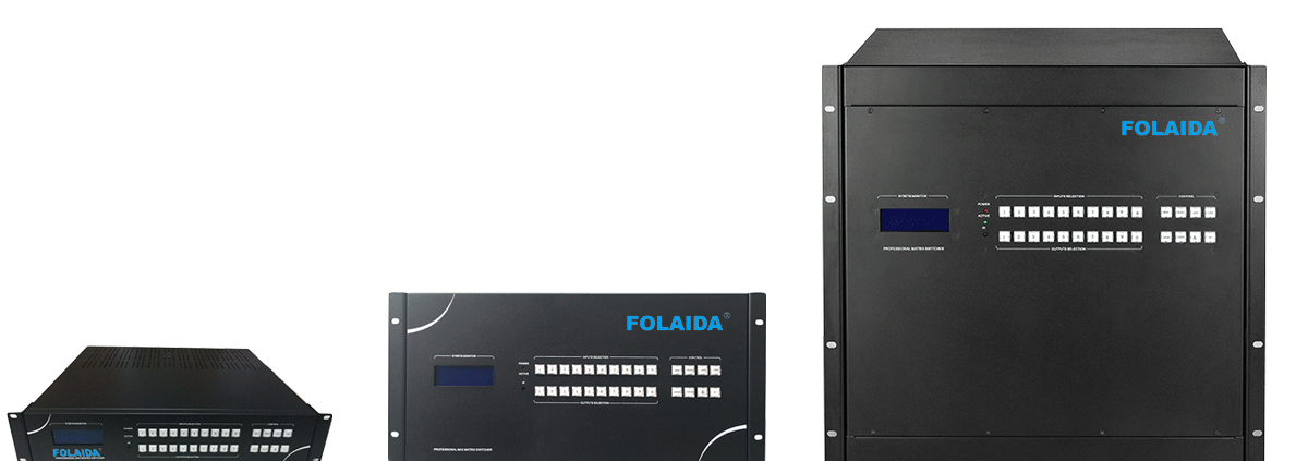
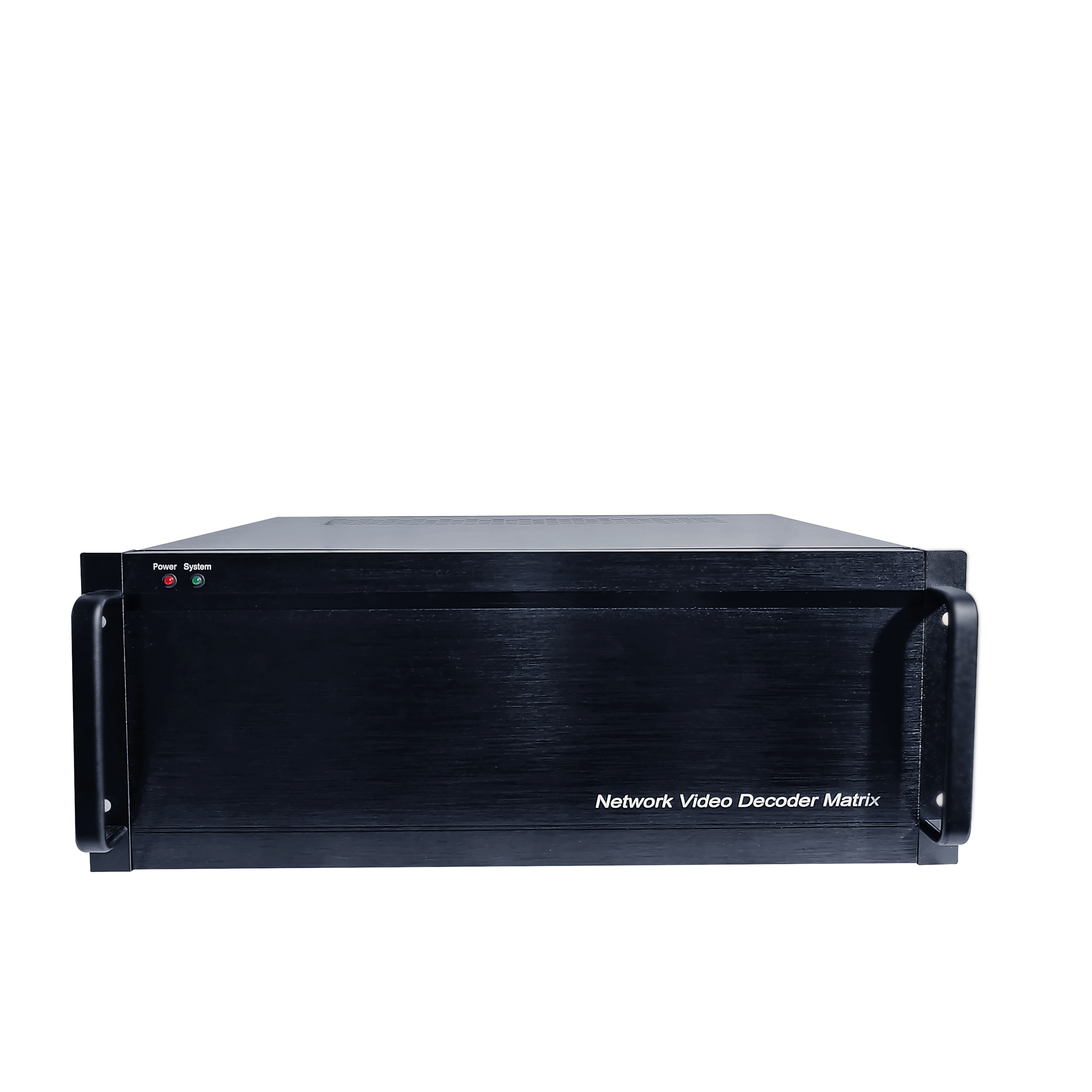
FOLAIDA network video decoder matrix rack-mount device with blue logo in the top-left corner and status LEDs nearby.

For display system planners, the word “solution” can be useful, but it can also become too broad if it is treated as a promise of full project design, installation, network deployment, and ongoing operation. In a multi-screen display system, the practical question is narrower: how do signal sources enter the processor, how are images routed and arranged, how do outputs reach the display wall, and how do operators control layouts after the system is built? This article maps those component relationships so planners can read video wall processor solution descriptions with clearer technical boundaries.

A video wall processor solution starts with sources, processing, and display outputs

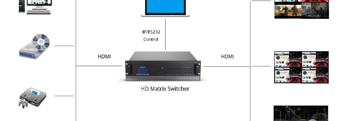
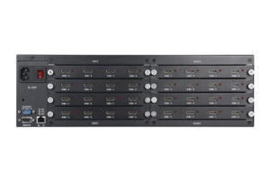
A video wall processor solution for multi-screen display systems begins with the relationship between signal sources and display destinations. Sources may include computers, media players, cameras, HDMI feeds, VGA or YPbPr devices, and IP streaming inputs when the processor supports them. The processor does not create the project purpose by itself; it receives these signals, manages routing and image treatment, and sends output signals toward a display wall or monitor array. That distinction matters because a source plan is still separate from content strategy, operator workflow, screen mounting, electrical planning, and network policy. The processor sits in the signal path, but it is not the entire system environment. The processing layer is where the term “solution” gains most of its technical meaning. Industry descriptions of video wall processing commonly center on functions such as scaling, windowing, image distribution, and arranging content across multiple displays. In a modular HDMI video wall processor, this layer may also involve input boards, output boards, a main control board, serial expansion, and power configuration. These parts are not interchangeable labels. Input cards define what kinds of source signals can be accepted; processing resources influence how images can be resized, combined, or positioned; output cards determine how signals are delivered to screens. A planner should therefore read the processor as a component map, not simply as a box with a product name. Outputs complete the visible side of the chain. A display wall needs the right number and type of output signals, but the final visual result also depends on screen layout, bezel arrangement, resolution matching, and how the processor maps source content across the array. A processor that supports video wall splicing, matrix switching, window movement, or picture-in-picture can help manage that layout, yet those function names do not automatically prove a specific project topology or screen count. The safer interpretation is that the processor provides display management capabilities that need to be matched with the actual source formats, output boards, screen arrangement, and operating expectations.

Control methods shape how layouts are managed after the signal path is built

Once the signal path is defined, control methods determine how people interact with the processor. RS232, LAN software, WebGUI, Windows, Android, and network control are not just marketing variations; they describe different operation entrances. RS232 generally points to serial device control and is often used when equipment needs command-based integration with control systems. LAN software suggests operation through a local network and vendor software environment. WebGUI usually means the user interacts with a web-based interface through a browser-like path, supported by web server mechanics in which a device or server responds to interface requests over a network. These terms help planners understand the control surface, but they do not by themselves confirm user permissions, cybersecurity policy, control distance, or every available function inside the interface. Control also changes how display layouts are handled over time. In a multi-screen system, the initial wiring may be stable, but operators often need to switch sources, recall layouts, move windows, preview signals, or adjust scenes. A control method provides the route for those actions. If a processor supports WebGUI and network control, for example, that may make browser-based or network-connected operation possible in principle, but the actual deployment still depends on IP addressing, access rules, supported browsers or client devices, and the site’s network management practices. The important boundary is that control access enables operation of processor functions; it does not automatically design the project’s content policy, user hierarchy, or IT security model. For planners, the most useful mental model is to separate the control path from the video path. The video path moves images from source inputs through processing to display outputs. The control path sends instructions to the processor so layouts, routes, and scenes can change. The two paths affect each other operationally, but they solve different problems. A signal may be technically routable even if the operator interface is not convenient for daily use; conversely, a convenient WebGUI does not remove the need to confirm input/output configuration, display mapping, resolution handling, and network conditions. Treating control as its own module helps prevent the word “solution” from expanding into assumptions the processor documentation may not support.

FOLAIDA page examples show how solution language should stay factual

FOLAIDA’s HDMI Video Wall Processor page is useful as a page-level example of how solution wording can be grounded in visible function terms. The page identifies a modular HDMI video wall processor and lists functions such as matrix switching, video wall splicing, windowing, image roaming, overlay, scaling, preview, drag-and-drop operation, picture-in-picture, OSD character overlay, subtitles, screen groups, scene modes, RS232, LAN software, Windows, Android, WebGUI, and network control. These details can help a planner connect product terms with the system modules described above. They should still be read as product function descriptions, not as confirmation of complete project design, installation, commissioning, training, or service delivery.

  • Video wall splicing connects processor output behavior with the physical display wall. It indicates that the processor can help divide or combine visual content across multiple screens, while the actual display arrangement and usable layout still depend on configured outputs, screen geometry, and project conditions.
  • Windowing and image roaming describe how content can be resized, moved, layered, or positioned within the display area. These terms belong to the display management layer, so they should not be confused with source compatibility guarantees or with final operator experience under every signal condition.
  • Screen groups and scene modes show how layout memory can become part of daily operation. The FOLAIDA page lists support for up to four display wall settings and up to 32 scenes, which helps explain how saved arrangements fit into a processor solution without proving every possible project workflow.
  • Network and software control terms identify operation entrances rather than full IT deployment. RS232, LAN software, Windows, Android, WebGUI, and network control can describe ways to operate the processor, while network security, access permissions, distance limits, and site integration remain conditions to confirm separately.

This factual reading protects both technical clarity and planning accuracy. In this sense, solution language is most reliable when it names visible modules: input options, processing functions, output configuration, control paths, and layout management. It becomes less reliable when it implies an entire installed system without showing the project drawings, cabling plan, network architecture, acceptance criteria, or service scope behind that claim.

Conclusion

A video wall processor solution is most useful when read as a system map. The core modules are signal inputs, processing functions, display outputs, control methods, and layout management. Together, they explain how multi-screen display systems route, resize, arrange, and operate visual content. They do not automatically confirm installation, project delivery, cybersecurity design, training, or long-term support. For readers comparing terminology, the FOLAIDA HDMI Video Wall Processor page can serve as a practical example of how functions such as splicing, windowing, scene modes, RS232, LAN software, WebGUI, and network control appear in product-level wording.

FAQ

 Q:What components are usually included in a video wall processor solution?

A:A video wall processor solution usually includes signal sources, processor hardware, input and output cards or ports, display wall outputs, control methods, and layout management functions. In practical planning, these should be separated into input, processing, output, control, and display layout modules, because the processor’s documented functions do not automatically include installation, content strategy, network design, or service delivery.

 Q:How does WebGUI control fit into a multi-screen display system?

A:WebGUI control is an operation path that lets users interact with processor functions through a web-based interface when the device and network conditions support it. It can help manage routing, layouts, or scenes, depending on the product’s implementation, but it should not be read as proof of a complete network deployment, security policy, permission structure, or full feature set without further confirmation.

 Q:Does a video wall processor solution automatically include installation and project delivery?

A:No. In product wording, a video wall processor solution usually refers to the processor’s role and related functions inside a multi-screen display system. Installation, cabling, screen mounting, network configuration, commissioning, operator training, warranty scope, and project delivery are separate service or project conditions that should be confirmed through specific documentation.

Sources / References

Extron Video Wall Processing

Texas Instruments – RS-232 Design Guide

What is a web server? – Learn web development | MDN
Related Examples

FOLAIDA HDMI Video Wall Processor product page

Modular hdmi video wall processors and hdmi signal routing basics

For product researchers comparing HDMI video wall processor specifications, the word modular can be both useful and misleading. It points to a card-based structure with input boards, output boards, control hardware, and processing functions, but it does not automatically define the final number of usable channels or confirm every display layout. A clearer reading starts with the physical and signal structure: where HDMI enters, how boards define available ports, how routing maps sources to screens, and where display negotiation can affect the final result.

How modular structure changes the way an HDMI video wall processor is described

In a modular HDMI video wall processor, the device is described less like a fixed input-output box and more like a chassis that accepts different functional boards. The important structural terms are the chassis, input boards, output boards, main control card, and expansion cards such as a serial communication card. This matters because a product description may list HDMI input boards, VGA/YPbPr input boards, mixed HDMI and VGA input boards, IP Streaming media input boards, DVI output boards, and HDMI output boards as available modules. Those terms describe how the processor can be built at the board level, not a guarantee that every possible board combination is available in one final project configuration. The modular idea also changes how a researcher should read interface claims. A fixed 4-input, 4-output processor is usually understood by its fixed ports. A card-based processor requires a different reading habit: first identify which board type is being discussed, then identify whether the figure refers to channels per board, supported interface type, resolution per interface, or chassis slot capacity. FOLAIDA’s HDMI Video Wall Processor is a useful example because its public product information presents a modular, card-based product with HDMI, VGA/YPbPr, mixed HDMI/VGA, and IP streaming input options, plus DVI and HDMI output board options. That structure helps explain the category, but it should not be stretched into a claim of unlimited routing, arbitrary expansion, or confirmed compatibility with every source and display. The word modular therefore works as a structure clue rather than a final engineering answer. It tells the reader that the processor can be described through replaceable or configurable boards, and that the input side and output side may be discussed separately. It does not replace the need to confirm the exact card population, usable input-output count, supported HDMI version per board, audio output scope, power configuration, or project topology. For a product researcher, the value of modular wording is that it makes the signal chain visible: sources enter through input boards, the processor performs routing and video wall management, and output boards send the selected signals to the display wall.

HDMI routing depends on input boards, output boards, and display negotiation

HDMI signal routing is the path by which a source signal is accepted, processed, assigned, and sent to one or more display outputs. In a video wall processor, this is closely related to matrix switching: the system can route available input signals to available output ports according to the processor’s supported switching and display management functions. In product wording, “all input signals can be switched to all output ports” is a routing concept. It does not mean every source will behave identically under every resolution, refresh rate, content protection condition, cable run, or display brand combination. HDMI is a standardized interface family, and each implementation still depends on the specific port, board, chipset, firmware, display, and content source involved.

Input and output board descriptions should stay tied to listed interfaces

A reliable reading keeps each board description attached to the listed interface instead of merging all interfaces into one generic capability. If an HDMI input board is described with HDMI Type A, HDCP support, and a stated resolution such as 1920×1080@60Hz, that information should be read as the interface-level description for that board. If an HDMI output board is described with HDMI Type A, HDMI 1.3, HDCP, optional audio output, and 1920×1080@60Hz, those details belong to that output board. DVI output boards, VGA/YPbPr input boards, and IP Streaming media input boards should be read in the same careful way. The processor may sit in one chassis, but its routing ability is still expressed through the boards and interfaces actually configured.

EDID and display negotiation can affect how specifications are understood

Display negotiation is another reason routing cannot be read only as a port count. In HDMI and DVI systems, EDID helps a source understand what a display or downstream device can accept, including resolution and timing information. In a video wall path, the source, processor, and displays may all influence how a signal is recognized and delivered. This does not mean EDID is a defect or a special limitation; it is part of normal digital display communication. It does mean that a specification such as HDMI input, HDCP support, or 4K@30Hz input should be treated as a stated capability that still needs to be matched with the actual source, display wall, board configuration, and content conditions. The practical lesson is that HDMI routing is both structural and negotiated. The structure tells you which physical boards and ports are available. The negotiation tells you whether a given source and display path can agree on usable parameters. A modular HDMI video wall processor may provide the routing architecture for many display wall tasks, including switching, splicing, window placement, scaling, and assigning content to multiple screens. But the final behavior of a specific HDMI source across multiple outputs depends on more than the processor name. It depends on the board specification, the display resolution, the source signal, HDCP conditions, and the way the video wall layout is configured.

Why a supplier page can educate without proving every project configuration

A public HDMI video wall processor supplier page can be valuable for understanding product facts because it often names the processor type, listed boards, visible interfaces, control methods, and function terms. For a product researcher, this is enough to build a first-level structure map: the device is modular, the input side may include HDMI and other signal types, the output side may include DVI or HDMI boards, and the processor may support matrix switching and video wall display management. This is educational because it connects vocabulary to visible product structure rather than leaving terms such as modular, HDMI input, and matrix routing floating as isolated claims. At the same time, a supplier page should not be treated as a complete project configuration document unless it clearly provides that level of detail. When a page lists modular boards, it may not state the final card combination rules for every chassis. When it lists HDMI and DVI output options, it may not confirm every possible display wall layout. When it mentions 2K/4K I/O or 4K@30Hz input, it should not be turned into a broad claim that all inputs, outputs, and layouts operate as a full 4K video wall processor under all conditions. Product pages are strongest when used as evidence for the terms and specifications they actually state; they are weaker when used to infer missing topology, compatibility, or performance guarantees. This distinction is especially important in B2B display projects, where a video wall processor solution may be discussed alongside screens, cabling, signal sources, control paths, and installation requirements. A researcher can use a product page to understand whether a processor belongs to the modular HDMI category and whether its published options align with a likely signal path. But details such as maximum effective input-output count, final card population, HDMI version compatibility, audio output applicability, IP streaming decoding behavior, and site-specific display negotiation should be confirmed through project documentation or direct technical communication. The supplier identity helps identify where the product facts come from; it should not turn the article into a supplier comparison or a shortcut for final system validation. The best way to use a page such as FOLAIDA’s HDMI Video Wall Processor information is as a specification reading example. It shows how modular boards, HDMI input, DVI/HDMI output options, and matrix switching terms can fit into one product description. It also reminds the reader to separate confirmed page-level facts from project-level conclusions. That balanced reading is more useful than either dismissing product pages as marketing or treating every feature phrase as a complete engineering guarantee.

Conclusion

A modular HDMI video wall processor is easiest to understand as a card-based signal management structure. The chassis provides the physical platform, input boards define how sources enter, output boards define how signals leave, and routing logic determines how available inputs can be assigned to display outputs. HDMI routing also depends on display negotiation, EDID behavior, HDCP conditions, and the exact board configuration. For product researchers, the most useful approach is to read supplier information as a source of product facts and interface options while keeping final channel counts, compatibility, and project layouts within a confirmation boundary.

FAQ

 Q:What makes an HDMI video wall processor modular?

A:An HDMI video wall processor is modular when its structure is organized around a chassis and functional boards rather than only fixed built-in ports. Input boards, output boards, a main control card, and possible expansion cards define how signals enter, leave, and are managed. This helps researchers understand the processor as a configurable signal platform, but the exact usable configuration still depends on the listed board options and project-specific confirmation.

 Q:Does a modular HDMI video wall processor mean unlimited input and output expansion?

A:No. Modular structure does not mean unlimited expansion, arbitrary compatibility, or unrestricted channel growth. It means the processor is described through boards and chassis capacity, but the final number of effective inputs and outputs depends on the supported card types, available slots, firmware behavior, interface specifications, power design, and the configuration confirmed for a specific project.

 Q:Why do input boards and output boards matter for HDMI signal routing?

A:Input boards determine which source signals can enter the processor, while output boards determine how processed signals are delivered to the display wall. HDMI routing depends on both sides because a processor cannot route a signal path that is not supported by the configured boards and interfaces. Board-level specifications also help clarify resolution, HDCP, connector type, and display compatibility boundaries.

Sources / References

HDMI Technology: Specifications and Programs

Video Wall Processing

Video wall processor solutions for control rooms training rooms and commercial displays

Commercial display project researchers often meet the term while comparing control room displays, training room systems, enterprise presentation spaces, and public-facing video walls. The useful question is not whether the word “solution” describes a complete project package. It is whether the room needs multi-source input, window management, screen grouping, scene recall, preview, drag-and-drop operation, or picture-in-picture viewing to make a display wall practical.
Where a Video Wall Processor Solution Fits in Display Tasks
In a control room, a video wall processor solution becomes relevant when operators need to observe several sources at the same time instead of switching one full-screen image after another. The task may involve dashboards, camera feeds, maps, alarm views, status screens, or workstation outputs on a shared display wall. In that setting, windowing and roaming are not decorative functions. They allow one source to stay large while secondary sources remain visible, so the video wall becomes a working surface rather than a passive screen. General video wall processing knowledge supports this role because processors are commonly associated with scaling, windowing, signal distribution, and multi-display image handling. That industry role explains the application category without turning a product page into a record of a specific control room deployment. Training rooms create a different display problem. The priority is often switching between presentation content, simulation content, live input, and instructor-controlled reference material without breaking the session rhythm. A processor can support this by making layouts repeatable. One scene may emphasize the instructor feed, another may enlarge a software interface, and another may combine several views for discussion. FOLAIDA’s HDMI Video Wall Processor page uses terms such as display walls, monitor arrays, video wall systems, screen groups, up to 32 scene modes, preview, drag-and-drop operation, picture-in-picture, windowing, roaming, overlay, and scaling. These terms are useful for understanding task fit in education and training spaces, while the exact room layout, source count, and card configuration remain project-specific. For this reason, saved layouts, clear source priority, and predictable recall behavior matter more than a broad claim of flexibility. Commercial display projects add a third pattern. Retail, exhibition, lobby, entertainment, and corporate display environments often care about visual composition: a large background image, a product video, a live feed, and several graphic zones may need to appear across one wall. Here, the processor’s value is not only the number of inputs or outputs. It is the ability to shape content across screens, create different screen groups, and recall layouts for different display moments. This is why a video wall processor for commercial display projects is often researched together with matrix switching, video wall splicing, window management, and scene modes. The same vocabulary may appear on a product page, but in scenario research those terms work best as application clues rather than statements about manufacturing scale, supply terms, or completed project delivery.
How Multi-Source Viewing, Window Management, and Scene Modes Map to Daily Use
A practical way to judge a video wall processor solution is to start from the display behavior users expect during operation. Interface names such as HDMI, VGA, YPbPr, IP streaming input, RS232, LAN software, or WebGUI matter when they explain how sources enter the system or how layouts are controlled. For scenario research, the deeper question is which display task would become difficult without processor-level control.
•Multi-source viewing is useful when the display wall must show several live or prepared feeds at once. A control room may need cameras and dashboards together, while a training space may need presentation slides beside a software interface. The processor’s role is to make those sources visible in useful proportions, not merely to connect cables.
•Window management matters when content size and position change during use. Resizing, moving, roaming, overlay, and scaling help a team adapt the display wall to the current discussion, monitoring priority, or presentation moment. This differs from a simple splitter that only repeats or divides a fixed signal.
•Screen groups help when one processor is expected to manage different display areas or wall sections. A commercial venue may want one group for brand content and another for live information, while a training room may separate instructor material from participant-facing visuals. The value is layout organization, not a blanket statement about any screen count.
•Scene modes are useful when teams need repeatable layouts. If a room regularly shifts between monitoring, briefing, training, demonstration, and review, saved scenes reduce manual adjustment. FOLAIDA’s page-level function terms, including screen groups and up to 32 scenes, are relevant here, while the usable configuration depends on hardware selection and project design.
IP streaming and WebGUI wording should also be read through tasks. RTSP provides a common technical background for real-time streaming control in IP video environments, but a product’s protocol list, camera compatibility, network topology, and decoding behavior should be checked against its technical documents. Likewise, a WebGUI normally implies interaction through a web-based interface served over a network connection, but it does not define remote access policy, cybersecurity design, or usability in every project environment. For project research, these terms are useful starting points for understanding control and input options, not final acceptance criteria.
Application Terms That Should Stay Conservative in Project Research
Application words such as government projects, enterprise projects, commercial display, entertainment, education and training, simulation training, modeling, high-resolution video monitoring, and graphics-intensive applications can help researchers understand where a video wall processor may be considered. They should not be rewritten as case studies without a separate case record or project document. This distinction matters in B2B content because readers may use application wording to shortlist products, discuss requirements internally, or prepare technical questions for a supplier. A careful description can say that these terms indicate relevant display environments. It should not say that the processor has been accepted in a specific government, medical, transportation, fire safety, or emergency command project unless that project record is available. The same caution applies to fixed-size search phrases such as 16×16 HDMI Video Wall Processor. A keyword like that may describe how a researcher imagines an input-output scale, but it is not the same as a documented product layout, card combination, or final screen arrangement. FOLAIDA’s processor information includes modular chassis, input and output card concepts, screen groups, windowing, scene modes, and several control approaches. The 16×16 phrase should remain search vocabulary unless the exact configuration is shown in the specification or project design. This matters because video wall systems are shaped by source count, display count, resolution, interface type, content behavior, operator workflow, and installation design. Treating a keyword as a layout can create mismatched expectations before technical discussion begins. The strongest use of scenario wording is task mapping. If the project needs many sources visible at once, window management becomes relevant. If the same room has recurring operating modes, scenes become relevant. If different parts of a display wall must behave independently, screen groups become relevant. If users need to arrange content actively during meetings, training, or monitoring sessions, preview and drag-and-drop functions become relevant. When those needs are absent, a full processor may be more than the display task requires. This approach keeps the article useful for commercial display research while keeping application terms separate from project evidence, industry compliance, and fixed hardware layouts.
Conclusion
A video wall processor solution should be evaluated by the display tasks it helps manage: multi-source viewing, window movement, screen grouping, scene recall, preview, drag-and-drop control, and picture-in-picture presentation. Control rooms, training rooms, and commercial display spaces may use these capabilities differently, so the best first step is to describe the intended screen behavior before assuming a fixed layout or industry deployment. FOLAIDA’s HDMI Video Wall Processor page provides relevant function and application vocabulary for this research, while detailed configuration, project layout, compatibility, and acceptance requirements should be checked separately. For a buyer or researcher, that distinction keeps the discussion practical and prevents a search term from being mistaken for an engineering result.
FAQ
Q:What does video wall processor solution mean in a commercial display project?
A:It usually means a processor-based approach for handling multiple sources, arranging content across several displays, managing windows, and recalling display layouts. In a commercial display project, the word “solution” should be read as an application fit around display tasks, not as automatic proof of a complete engineering package, finished installation, or final project configuration.
Q:Which display tasks make window management and scene modes useful?
A:Window management is useful when operators, instructors, or presenters need to resize, move, overlay, or compare several sources on the same display wall. Scene modes become useful when the room repeats several layouts, such as monitoring, briefing, teaching, demonstration, or public display playback, and users need to recall those layouts without rebuilding them manually.
Q:Does a 16×16 HDMI Video Wall Processor keyword prove a confirmed product layout?
A:No. A phrase such as 16×16 HDMI Video Wall Processor can reflect how a buyer searches for a fixed input-output scale, but it does not establish that a specific product page, chassis, card combination, or project design uses that exact layout. The actual configuration should be checked against documented specifications and project requirements.
Sources / References
Video Wall Processing
RFC 2326: Real Time Streaming Protocol
What is a web server?
Related Examples
FOLAIDA 4K Modular HDMI Video Wall Processor

How to Choose the Right HDMI Matrix Switch for Conference Rooms

Modern conference rooms are no longer simple meeting spaces. Businesses today use multiple laptops, wireless presentation systems, cameras, displays, and collaboration devices to create efficient communication environments.https://folaida.com/product-item/hd-matrix-switcher/

With multiple HDMI sources and multiple displays, managing video signals becomes a challenge.

A professional HDMI Matrix Switch for Conference Rooms provides a reliable solution by allowing multiple HDMI sources to connect with multiple displays and enabling flexible source switching.

Unlike an HDMI splitter, which only duplicates one signal to multiple screens, an HDMI Matrix Switch allows each display to show different content from different sources.

For corporate meeting rooms, training rooms, and conference centers, HDMI Matrix technology provides:

  • Flexible signal routing
  • Centralized control
  • Multiple display management
  • High-resolution video distribution
  • Scalable AV system expansion

What Is an HDMI Matrix Switch for Conference Rooms?

An HDMI Matrix Switch is a professional AV device that connects multiple HDMI input sources with multiple HDMI output displays.

The matrix allows users to independently select which source appears on each display.

For example, a conference room may include:

HDMI Sources:

  • Laptop 1
  • Laptop 2
  • Conference camera
  • Media player
  • Wireless presentation system

Displays:

  • Main presentation screen
  • Confidence monitor
  • Side displays
  • Video wall

An HDMI Matrix allows any source to be routed to any display.

Example:

Laptop 1  ─┐
Laptop 2  ─┤
Camera    ─┤── HDMI Matrix Switch ── Display 1
Player    ─┘                       ── Display 2
                                     ── Display 3

This creates a flexible and professional conference room AV system.


Why Use HDMI Matrix in Conference Rooms?

1. Multiple Presenters Need Flexible Switching

In modern meetings, different users may need to share content.

A conference room may have:

  • Executive laptop
  • Guest laptop
  • Presentation computer
  • Video conferencing system

An HDMI Matrix Switch allows users to instantly switch between different sources without reconnecting cables.

This improves meeting efficiency and reduces setup time.


2. Multiple Displays Require Independent Control

Large conference rooms often include multiple displays.

Examples:

  • Main display
  • Rear display
  • Side monitor
  • Video wall

With an HDMI Matrix:

Display 1 can show:

Presentation Computer

Display 2 can show:

Video Conference Camera

Display 3 can show:

Meeting Notes

Each display can receive different content.


3. Better Integration With Video Conferencing Systems

Modern conference rooms combine:

  • Microsoft Teams Rooms
  • Zoom Rooms
  • Cameras
  • Microphones
  • Displays

An HDMI Matrix Switch helps integrate different AV devices into one centralized system.

It enables:

  • Easy source switching
  • Display management
  • Professional control integration

How to Choose the Right HDMI Matrix Switch for a Conference Room

Choosing the correct HDMI Matrix depends on several important factors.


1. Determine the Number of HDMI Inputs and Outputs

The first step is calculating how many devices and displays need connection.

Small Conference Room

Recommended:

4×4 HDMI Matrix Switch

Suitable for:

  • Small meeting rooms
  • Huddle rooms
  • Training rooms

Example:

Inputs:

  • 2 laptops
  • 1 camera
  • 1 media player

Outputs:

  • Main display
  • Secondary display
  • Projector
  • Monitor

Medium Conference Room

Recommended:

8×8 HDMI Matrix Switch

Suitable for:

  • Corporate meeting rooms
  • Boardrooms
  • Training centers

Supports:

  • Multiple presenters
  • Multiple displays
  • Advanced AV systems

Large Conference Room

Recommended:

16×16 HDMI Matrix Switch

Suitable for:

  • Conference centers
  • Enterprise headquarters
  • Multi-room AV systems

2. Choose the Right HDMI Resolution

Resolution is a critical factor when selecting an HDMI Matrix.

Modern conference rooms should consider:

4K HDMI Matrix Switch

Recommended for:

  • Corporate presentations
  • High-quality video conferencing
  • Large displays

Features:

  • 4K@60Hz support
  • HDR compatibility
  • HDCP 2.2

8K HDMI Matrix Switch

Recommended for future-ready AV systems.

Features:

  • HDMI 2.1 support
  • Higher bandwidth
  • Next-generation displays

3. Consider Control Methods

Professional conference rooms require simple and reliable control.

Common HDMI Matrix control methods include:

Front Panel Control

Suitable for:

  • Small rooms
  • Simple installations

Remote Control

Allows users to switch sources remotely.

RS232 Control

Commonly integrated with:

  • Crestron
  • Extron
  • AMX control systems

TCP/IP Network Control

Ideal for:

  • Enterprise AV systems
  • Multiple meeting rooms
  • Central management

4. Check EDID Management Capability

EDID management is an important feature in professional HDMI Matrix systems.

It helps communication between:

  • HDMI sources
  • Matrix switch
  • Displays

Benefits:

  • Prevents compatibility problems
  • Improves system stability
  • Supports different display resolutions

For commercial conference rooms, EDID management is highly recommended.


5. Consider Seamless Switching

During important meetings, black screens or signal interruptions can affect user experience.

Professional HDMI Matrix Switches with seamless switching provide:

  • Smooth source changes
  • Faster switching speed
  • Better presentation experience

This is especially important for:

  • Executive meeting rooms
  • Boardrooms
  • Live presentations

HDMI Matrix vs HDMI Switch for Conference Rooms

Many users confuse HDMI Matrix with HDMI Switch.

HDMI Switch

An HDMI Switch:

  • Multiple inputs
  • One output

Example:

Laptop 1
Laptop 2
Laptop 3

↓

HDMI Switch

↓

One Display

Suitable for simple applications.


HDMI Matrix

An HDMI Matrix:

  • Multiple inputs
  • Multiple outputs
  • Independent routing

Example:

Laptop 1
Laptop 2
Camera

↓

HDMI Matrix

↓

Multiple Displays

Suitable for professional conference rooms.


Recommended Conference Room HDMI Matrix System Design

A typical professional conference room may include:

HDMI Sources

  • Presentation laptops
  • Wireless presentation device
  • Camera system
  • Media player

HDMI Matrix Switch

Displays

  • Main screen
  • Side monitors
  • Projector
  • Video wall

Control System

  • Touch panel
  • Room controller
  • Network management

This creates a complete conference room AV solution.


Common Conference Room Applications

Executive Boardroom

Requirements:

  • High reliability
  • Multiple displays
  • Easy control

Recommended:

4×4 or 8×8 HDMI Matrix


Training Room

Requirements:

  • Multiple presenters
  • Multiple screens
  • Flexible switching

Recommended:

8×8 HDMI Matrix


Conference Center

Requirements:

  • Large-scale distribution
  • Multiple rooms
  • Central control

Recommended:

16×16 or larger HDMI Matrix


Why Choose FOLAIDA HDMI Matrix Solutions?

FOLAIDA provides professional HDMI Matrix Switch solutions designed for conference rooms and commercial AV applications.

Our solutions support:

  • 4K and 8K HDMI distribution
  • Multiple input/output configurations
  • EDID management
  • Seamless switching
  • RS232 and TCP/IP control
  • Integration with professional AV systems

FOLAIDA HDMI Matrix products help AV integrators build reliable and scalable conference room solutions worldwide.


Frequently Asked Questions

Do conference rooms need an HDMI Matrix?

If a conference room has multiple HDMI sources and multiple displays, an HDMI Matrix provides better flexibility and control than traditional HDMI switches or splitters.


What size HDMI Matrix do I need for a meeting room?

Small rooms usually use 4×4 HDMI Matrix systems. Medium and large conference rooms may require 8×8, 16×16, or larger systems.


Can HDMI Matrix support wireless presentation systems?

Yes. Professional HDMI Matrix systems can integrate with wireless presentation devices.


Does HDMI Matrix support video conferencing?

Yes. HDMI Matrix systems are commonly used with cameras, conferencing systems, and multiple displays.


Conclusion

Choosing the right HDMI Matrix Switch for Conference Rooms depends on your number of sources, displays, resolution requirements, control methods, and future expansion plans.

For simple rooms, a small HDMI Matrix may be enough.

For professional corporate environments, conference centers, and enterprise AV systems, an HDMI Matrix provides the flexibility, reliability, and scalability needed for modern collaboration.

A properly designed HDMI Matrix solution creates a smarter, more efficient, and future-ready conference room experience.https://studio.youtube.com/video/2aDKrQsPr20/edit

HDMI Matrix vs HDMI Splitter: Complete Comparison Guide Introduction: HDMI Matrix vs HDMI Splitter

When designing a professional audio and video system, one common question is:

Should I use an HDMI Matrix Switch or an HDMI Splitter?

Although both devices distribute HDMI signals to multiple displays, they serve completely different purposes.

An HDMI Splitter duplicates one HDMI source signal to multiple displays, while an HDMI Matrix Switch allows multiple HDMI sources to be independently routed to multiple displays.

Choosing the right solution depends on your application, system size, control requirements, and future expansion needs.

In this guide, we will explain the differences between HDMI Matrix and HDMI Splitter, their advantages, applications, and how to choose the right solution for professional AV systems.https://folaida.com/product-item/hd-matrix-switcher/


What Is an HDMI Matrix?

An HDMI Matrix Switch is a professional AV signal routing device that connects multiple HDMI sources with multiple HDMI displays and provides flexible signal switching and distribution.

An HDMI Matrix allows users to select:

  • Which source is displayed on each screen
  • Different content on different displays
  • Multiple sources distributed simultaneously

For example:

A 4×4 HDMI Matrix Switch supports:

  • 4 HDMI input sources
  • 4 HDMI output displays

Any input can be routed to any output.

Example:

Input Sources:

PC 1
PC 2
Camera
Media Player


        ↓


HDMI Matrix Switch


        ↓


Displays:

Screen 1 → PC 1

Screen 2 → Camera

Screen 3 → Media Player

Screen 4 → PC 2

This flexibility makes HDMI Matrix systems ideal for professional AV environments.


What Is an HDMI Splitter?

An HDMI Splitter is a device that takes one HDMI input signal and duplicates it to multiple HDMI outputs.

For example:

A 1×4 HDMI Splitter:

  • 1 HDMI input
  • 4 HDMI outputs

Signal flow:

One HDMI Source

        ↓

HDMI Splitter

        ↓

Display 1
Display 2
Display 3
Display 4

All displays receive the same content.

Example:

A company wants the same presentation displayed on four TVs in different rooms.

An HDMI Splitter can easily achieve this.


HDMI Matrix vs HDMI Splitter: Key Differences

Feature HDMI Matrix Switch HDMI Splitter
HDMI Inputs Multiple Usually One
HDMI Outputs Multiple Multiple
Signal Routing Independent Fixed Distribution
Different Content on Screens Yes No
Multiple Sources Yes No
Professional AV Applications Yes Limited
Video Wall Support Yes No
Control System Integration Yes Limited
Scalability High Low

Main Difference: Flexible Switching vs Signal Duplication

The biggest difference between HDMI Matrix and HDMI Splitter is how they handle HDMI signals.

HDMI Splitter

A splitter answers this question:

“How can I show the same content on multiple screens?”

Example:

One computer → Five displays

Applications:

  • Digital signage
  • Retail advertising
  • Information screens

HDMI Matrix

A matrix answers this question:

“How can I control multiple sources and multiple displays independently?”

Example:

Five computers → Ten displays

Each display can show different content.

Applications:

  • Conference rooms
  • Control centers
  • Training rooms
  • Broadcast studios

HDMI Matrix Advantages

1. Independent Source Selection

With an HDMI Matrix Switch, every display can select its own HDMI source.

Example:

Conference Room A:

Display 1 → Laptop

Display 2 → Camera

Conference Room B:

Display 3 → Media Player

Display 4 → PC


2. Professional Control Options

Commercial HDMI Matrix systems support:

  • Front panel control
  • Remote control
  • RS232 control
  • TCP/IP network control
  • Web interface
  • Third-party control systems

This makes HDMI Matrix suitable for integrated AV projects.


3. Supports Large AV Systems

HDMI Matrix solutions can be expanded from:

  • 4×4 HDMI Matrix
  • 8×8 HDMI Matrix
  • 16×16 HDMI Matrix
  • 32×32 HDMI Matrix

Large installations can manage dozens of HDMI sources and displays.


4. Better for Future Expansion

Professional AV projects often grow over time.

An HDMI Matrix provides:

  • More input options
  • More output options
  • Flexible system upgrades

HDMI Splitter Advantages

Although HDMI Splitters are less flexible, they are useful for simple applications.

1. Simple Installation

HDMI Splitters are easy to install:

One source → Multiple displays


2. Cost Effective

For basic applications, HDMI Splitters provide a lower-cost solution.


3. Ideal for Duplicate Display Systems

Common applications:

  • Retail stores
  • Exhibitions
  • Digital signage
  • Home entertainment

HDMI Matrix vs HDMI Splitter: Application Comparison

Conference Room

Recommended Solution:

✅ HDMI Matrix Switch

Why?

Modern conference rooms require:

  • Multiple laptops
  • Wireless presentation
  • Multiple displays
  • Flexible switching

Example:

Laptop 1 → Display 1

Laptop 2 → Display 2

Camera → Display 3


Control Room

Recommended Solution:

✅ Professional HDMI Matrix System

Control rooms require:

  • 24/7 operation
  • Multiple video sources
  • Multiple monitoring screens
  • Fast source switching

Digital Signage

Recommended Solution:

Depends on requirements.

Same content everywhere:

✅ HDMI Splitter

Different content:

✅ HDMI Matrix


Video Wall System

Recommended Solution:

✅ HDMI Matrix + Video Wall Processor

Professional video walls usually require flexible source management.


HDMI Matrix vs HDMI Splitter for 4K and 8K Systems

Modern AV systems require higher resolution support.

HDMI Matrix Features:

Professional HDMI Matrix Switches support:

  • 4K@60Hz
  • 8K HDMI 2.1
  • HDR
  • HDCP 2.2 / HDCP 2.3
  • EDID management

HDMI Splitter Features:

HDMI Splitters may support:

  • 4K resolution
  • Basic HDCP compatibility

However, advanced control features are usually limited.


How to Choose Between HDMI Matrix and HDMI Splitter?

Choose an HDMI Splitter if:

✔ You only need one HDMI source

✔ All displays show identical content

✔ Simple installation is required

Examples:

  • Store advertisements
  • Lobby displays
  • Home entertainment

Choose an HDMI Matrix if:

✔ You have multiple HDMI sources

✔ Displays need different content

✔ Professional control is required

✔ System expansion is expected

Examples:

  • Conference centers
  • Command centers
  • Education facilities
  • Corporate AV systems

Why Professional AV Integrators Prefer HDMI Matrix Solutions

Professional AV projects require more than simple signal duplication.

An HDMI Matrix provides:

  • Flexible signal routing
  • Centralized control
  • Reliable operation
  • Multi-display management
  • Easy system expansion

For commercial installations, HDMI Matrix Switches provide a scalable solution for modern AV distribution.


FOLAIDA Professional HDMI Matrix Solutions

FOLAIDA provides professional HDMI Matrix Switch solutions for global AV applications.

Our HDMI Matrix products support:

  • 4K and 8K HDMI distribution
  • Multiple input/output configurations
  • EDID management
  • Seamless switching
  • RS232 and IP control
  • Video wall integration

FOLAIDA HDMI Matrix solutions are designed for:

  • AV integrators
  • System installers
  • Distributors
  • Enterprise customers

Frequently Asked Questions

Is HDMI Matrix better than HDMI Splitter?

For professional AV systems, HDMI Matrix is usually better because it provides independent source switching and display control.


Can HDMI Splitter replace HDMI Matrix?

No. HDMI Splitter only duplicates signals and cannot independently control multiple sources.


Which is better for conference rooms?

HDMI Matrix is recommended because conference rooms often require multiple sources and displays.


Does HDMI Matrix support video walls?

Yes. HDMI Matrix systems are commonly used with video wall processors for professional display applications.


Conclusion

The difference between HDMI Matrix and HDMI Splitter comes down to flexibility.

An HDMI Splitter is designed for simple signal duplication:

One source → Multiple displays

An HDMI Matrix Switch is designed for professional AV management:

Multiple sources → Multiple displays with independent control

For small simple systems, an HDMI Splitter may be enough.

For conference rooms, control rooms, video walls, and commercial AV projects, an HDMI Matrix provides the flexibility, reliability, and scalability required for professional installations.https://studio.youtube.com/video/2aDKrQsPr20/edit


What is HDMI Matrix? A Complete Guide to HDMI Matrix Switch Systems

Introduction: What is HDMI Matrix?

https://folaida.com/product-item/hd-matrix-switcher/An HDMI Matrix is a professional AV signal routing device that allows multiple HDMI sources to connect with multiple displays and provides flexible control over signal distribution.

Unlike a standard HDMI splitter, which only sends one source signal to multiple screens, an HDMI Matrix Switch allows users to independently select different sources for different displays.

For example, a 4×4 HDMI Matrix can connect four HDMI input sources and four HDMI output displays, allowing any input device to be displayed on any output screen.

HDMI Matrix systems are widely used in:

  • Conference rooms
  • Control rooms
  • Video walls
  • Education facilities
  • Hotels
  • Broadcast studios
  • Command centers
  • Digital signage systems

Professional AV integrators choose HDMI Matrix solutions because they provide reliable signal management, flexible routing, and centralized control.


How Does an HDMI Matrix Switch Work?

An HDMI Matrix Switch works by receiving multiple HDMI input signals and routing them to multiple HDMI output devices.

The HDMI Matrix acts as the central hub of an AV distribution system.

Users can select:

  • Which source goes to which display
  • Multiple sources displayed simultaneously
  • One source displayed on multiple screens
  • Different content displayed in different rooms

HDMI Matrix Input and Output Explained

HDMI Matrix products are usually named according to their input and output numbers.

Examples:

4×4 HDMI Matrix Switch

A 4×4 HDMI Matrix provides:

  • 4 HDMI inputs
  • 4 HDMI outputs

It allows any of the four sources to be routed to any of the four displays.

Typical applications:

  • Small conference rooms
  • Training rooms
  • Meeting spaces

8×8 HDMI Matrix Switch

An 8×8 HDMI Matrix provides:

  • 8 HDMI inputs
  • 8 HDMI outputs

Common applications:

  • Corporate conference centers
  • Hotels
  • Educational facilities

16×16 HDMI Matrix Switch

A 16×16 HDMI Matrix is designed for larger AV installations.

Applications include:

  • Control centers
  • Government projects
  • Enterprise AV systems
  • Large meeting facilities

32×32 HDMI Matrix System

Large-scale HDMI Matrix systems support complex signal distribution.

They are commonly used in:

  • Command centers
  • Broadcast environments
  • Large video wall projects

HDMI Matrix vs HDMI Splitter: What Is the Difference?

Many customers confuse HDMI Matrix Switches with HDMI Splitters.

The main difference is signal flexibility.

Feature HDMI Matrix HDMI Splitter
Multiple Inputs Yes Usually No
Multiple Outputs Yes Yes
Independent Routing Yes No
Different Content on Different Screens Yes No
Professional AV Applications Yes Limited

An HDMI splitter can duplicate one HDMI source to multiple displays.

An HDMI Matrix allows users to control multiple sources and multiple displays independently.

For professional AV systems, HDMI Matrix provides much greater flexibility.


Key Features of Professional HDMI Matrix Switches

Modern HDMI Matrix systems include advanced features designed for commercial AV applications.

1. 4K and 8K Resolution Support

Professional HDMI Matrix Switches support high-resolution video formats including:

  • 4K@60Hz
  • 8K HDMI 2.1
  • HDR
  • Dolby Vision
  • HDCP 2.2 / HDCP 2.3

High-resolution support ensures excellent image quality for modern displays.


2. Seamless Switching

Seamless switching technology allows users to change between HDMI sources smoothly without black screens or signal interruption.

This is important for:

  • Control rooms
  • Live events
  • Conference presentations

3. EDID Management

EDID management helps HDMI Matrix systems communicate correctly with connected displays.

It improves:

  • Display compatibility
  • Resolution matching
  • System stability

4. Multiple Control Options

Professional HDMI Matrix Switches support various control methods:

  • Front panel buttons
  • Remote control
  • RS232 control
  • TCP/IP network control
  • Web interface
  • Third-party control systems

Where Are HDMI Matrix Systems Used?

Conference Room HDMI Matrix Solution

Modern meeting rooms often require multiple devices connected to multiple displays.

An HDMI Matrix allows:

  • Laptop sharing
  • Wireless presentation
  • Multiple display management
  • Centralized control

Control Room HDMI Matrix Solution

Control centers require reliable 24/7 operation.

HDMI Matrix systems provide:

  • Real-time video distribution
  • Multi-screen monitoring
  • Flexible source switching

Video Wall HDMI Matrix Solution

Video walls often require multiple video sources displayed across multiple screens.

HDMI Matrix systems help manage:

  • Multiple HDMI inputs
  • Large display systems
  • Different layouts

Education AV Systems

Schools and universities use HDMI Matrix solutions for:

  • Lecture halls
  • Training rooms
  • Multimedia classrooms

Hotel and Hospitality AV

Hotels use HDMI Matrix systems for:

  • Conference facilities
  • Event rooms
  • Digital signage

How to Choose the Right HDMI Matrix Switch?

Before selecting an HDMI Matrix, consider the following factors:

1. Number of Inputs and Outputs

Choose according to your system size.

Examples:

Small room:

  • 4×4 HDMI Matrix

Medium installation:

  • 8×8 HDMI Matrix

Large project:

  • 16×16 or 32×32 HDMI Matrix

2. Resolution Requirements

Consider:

  • 1080P
  • 4K
  • 8K

For future-proof systems, 4K and 8K HDMI Matrix solutions are recommended.


3. Control Requirements

Professional projects may require:

  • RS232
  • TCP/IP
  • API integration
  • Central control systems

4. Application Environment

Different applications require different solutions:

  • Conference room
  • Control room
  • Video wall
  • Broadcast
  • Digital signage

Why Choose FOLAIDA HDMI Matrix Solutions?

FOLAIDA provides professional HDMI Matrix Switch solutions designed for global commercial AV applications.

Our HDMI Matrix products support:

  • 4K/8K HDMI signal distribution
  • Multiple input/output configurations
  • EDID management
  • Seamless switching
  • RS232 and IP control
  • Customized AV solutions

FOLAIDA HDMI Matrix systems are widely used by AV integrators, distributors, and system installers worldwide.


Frequently Asked Questions About HDMI Matrix

What does HDMI Matrix mean?

HDMI Matrix means a device that allows multiple HDMI sources to connect with multiple displays and provides independent signal routing control.

Is HDMI Matrix better than HDMI Splitter?

Yes. HDMI Matrix provides flexible switching between multiple sources and displays, while HDMI Splitter only duplicates one source signal.

Can HDMI Matrix support 4K?

Yes. Many professional HDMI Matrix Switches support 4K@60Hz and advanced HDMI standards.

Can HDMI Matrix control video walls?

Yes. HDMI Matrix systems can be integrated with video wall processors and professional display systems.

What is the difference between HDMI Matrix and AV over IP?

HDMI Matrix uses dedicated hardware switching, while AV over IP distributes signals through network infrastructure. Both are used for professional AV distribution.


Conclusion

An HDMI Matrix Switch is the core component of many professional AV systems. It provides flexible HDMI signal routing, reliable video distribution, and centralized control for multiple displays.

From conference rooms and control centers to video walls and digital signage projects, HDMI Matrix solutions help organizations build efficient and scalable AV environments.

For professional HDMI Matrix systems, choosing the right manufacturer and solution partner is essential for long-term reliability and performance.https://studio.youtube.com/video/2aDKrQsPr20/edit

hdbaset matrix switcher

Rs232 And Tcp Ip Control Paths For Scalable Matrix Switcher Deployment

In a commercial HDMI matrix switcher project, control is not just a feature line in a specification sheet. It affects how installers test routing on site, how operators change sources after delivery, and how the integrator explains service responsibilities. For control rooms, meeting spaces, commercial displays, and multi-screen routing projects, the practical question is not whether buttons, IR remote, RS232, and optional TCP/IP control exist. The question is where each control path belongs in the workflow and what information must be confirmed with the HDMI matrix switcher supplier before deployment.

Map Control Methods to Installation, Testing, and Handover Stages

A scalable matrix switcher deployment usually moves through three control phases: local installation, commissioning verification, and operational handover. Front-panel buttons are useful at the earliest stage because they allow technicians to confirm that the chassis powers on, routes respond, and displays receive expected HDMI signals before external control systems are involved. IR remote control can also support basic functional checks, especially when the installer wants to demonstrate source switching without connecting a control processor. These methods are not the final control architecture, but they reduce confusion during the first hours of site work when cable labeling, display assignment, and source readiness are still being confirmed. RS232 control becomes more important when the integrator needs repeatable communication between the matrix switcher and a local control processor. At this stage, the goal is not only to switch sources but also to verify that command paths, cable runs, control ports, and operator scenarios match the system design. Optional TCP/IP control belongs later in the discussion unless the project already has a defined network scope, because network-based control depends on coordination with IT boundaries, addressing plans, access rules, and room control expectations. FOLAIDA’s FLD-HD-N Series Matrix Switcher presents buttons, IR remote, RS232, optional TCP/IP control, and APP control clues alongside a modular HDMI matrix switcher structure. That makes it reasonable for system integrators to separate immediate local testing from the final project control path. A button can prove that the matrix responds, but it does not validate a third-party control system. IR can support a demonstration, but it may not match the operator’s permanent control interface. RS232 can support predictable local integration, but it still requires the right control documentation and wiring conditions. TCP/IP can be attractive for larger projects, but it should not be assumed as standard or treated as a complete network management platform without confirmation. For an HDMI matrix switcher manufacturer conversation, the useful starting point is therefore the stage of work: install, test, commission, or hand over.

Decide When Serial Control or Network Control Better Fits the Project

The choice between RS232 and optional TCP/IP control should follow the project’s control responsibility, not a general preference for older or newer interfaces. Many integrators prefer serial control when a matrix switcher is located near a rack-based controller and the operating logic is local to one room or one equipment area. Network control becomes more relevant when the control system is already IP-based, when the control processor and matrix switcher may sit in different equipment zones, or when the owner expects centralized room operation through managed infrastructure. However, the more a control path depends on the network, the more the integrator must define the boundary between AV equipment, IT policy, and handover documentation.

RS232 Control Supports Predictable Local Integration During Commissioning

RS232 control is often practical when the system integrator wants a direct, point-to-point control path during commissioning. In a meeting room rack, command center display wall, or commercial display installation, this can simplify the first round of troubleshooting because the control link is physically traceable and usually separate from the client’s broader network. For an RS232 control HDMI matrix switcher deployment, the integrator should still confirm cable distance expectations, control port availability, command documentation, and responsibility for testing the control processor. The value of RS232 is predictability during local integration, not a promise that every controller, cable condition, or command set will work without project-specific verification.

Optional TCP IP Control Requires Clear Network Scope Before Deployment

TCP/IP control is better considered when the project already has a network-based control plan and the client can define how AV devices will connect to local infrastructure. For a TCP/IP control HDMI matrix switcher request, the integrator should be ready to discuss whether the matrix will sit on a dedicated AV LAN, a shared corporate network, or a restricted control subnet. This matters because control rooms and operational environments often require clear boundaries between systems, users, and device communication paths. Industry guidance on operational technology security supports the broader point that connected control environments benefit from defined segmentation and responsibility, although it does not replace product-specific control instructions from the matrix switcher manufacturer. The practical decision logic is straightforward. Use RS232 when local controller integration, direct cabling, and predictable commissioning are the dominant needs. Discuss optional TCP/IP when the project has network readiness, IT approval, and a defined expectation for how the operator will access the control interface. Keep front-panel buttons and IR remote in the workflow as installation and fallback tools, not as the entire control plan for a professional deployment. When APP control is mentioned, treat it as a control option to clarify with FOLAIDA rather than assuming a specific application name, software version, or device support model beyond the visible PC, tablet, and Android-related clues.

Connect Modular Matrix Hardware to Maintainable Project Communication

A modular HDMI matrix switcher changes the way integrators should communicate with a supplier because control is tied to system architecture, not only to the rear-panel connector. FOLAIDA’s FLD-HD-N Series is presented as a card-based design with chassis, input cards, output cards, PSUs, cooling fan, control cards, and network previewing card elements. For a system integrator, this structure suggests a more disciplined project conversation: which input and output scale is required, how many HDMI A female connections are expected, whether the system uses 4CH per card logic, what control card assumptions apply, and whether optional network-related functions are part of the requested configuration. It should not be expanded into claims about hot swapping, redundant power, or on-site quick repair unless the supplier confirms those details for the project. The communication benefit is that the integrator can separate signal routing questions from control-path questions. Signal routing covers source count, display count, resolution expectations, HDMI environment, and the role of the matrix in the larger AV system. Control-path discussion covers buttons, IR remote, RS232, optional TCP/IP, APP control clues, control documentation, cable access, rack location, and handover responsibilities. When speaking with an HDMI matrix switcher supplier, this separation helps prevent late-stage misunderstandings. A 32×32 or larger matrix may satisfy the routing scale, but the project can still fail at handover if the owner’s control interface, site network rules, and commissioning method were not aligned early. This is also where the role of an HDMI matrix switcher manufacturer becomes more specific. The integrator should not simply ask whether the product “supports control.” A better inquiry explains the controller type, expected operator interface, network boundary if TCP/IP is requested, number of displays, number of HDMI sources, intended matrix size, and the documents needed for commissioning. If the project involves a control room or operational display environment, the integrator should also clarify who validates the control path during acceptance testing and who keeps the final routing and control records. FOLAIDA can be approached in this context as a matrix switcher manufacturer for project confirmation, while the integrator remains responsible for translating equipment capabilities into a workable site deployment plan.

Conclusion

Control paths should be planned as a workflow, not treated as isolated features. Buttons and IR remote support local installation checks, RS232 can provide a predictable path for local commissioning, and optional TCP/IP control should be discussed only after the project network scope is clear. For scalable AV integration, system integrators should contact FOLAIDA with the control system type, network boundary, primary control method, display count, source count, matrix size, and handover documentation needs so the control approach can match the actual deployment.

FAQ

 Q:When should a system integrator use RS232 control for an HDMI matrix switcher deployment?

A:RS232 control is usually appropriate when the matrix switcher is being integrated with a local rack-based control processor and the integrator wants a direct, traceable communication path during commissioning. It works best when the control equipment is close enough for planned cabling, the command documentation can be confirmed, and the project does not require the matrix to be managed through a broader IP network.

 Q:What project information should be confirmed before requesting optional TCP/IP control from FOLAIDA?

A:Before requesting optional TCP/IP control, integrators should confirm the project’s network boundary, whether the device will connect to a dedicated AV LAN or shared network, who manages IP addressing, what operator interface is expected, and whether IT approval is required. They should also share the control system type, display count, source count, matrix size, and commissioning documentation needs.

 Q:How does modular design affect control-path communication with an HDMI matrix switcher supplier?

A:Modular design makes supplier communication more configuration-focused because the integrator must discuss the chassis, input cards, output cards, control cards, and any network-related options as part of the project plan. It helps separate routing scale from control-path requirements, but it should not be interpreted as hot-swappable or redundant capability unless the supplier confirms those functions for the specific project.

Sources / References

HDMI Resources Overview

HDMI Technology Specifications and Programs

SP 800-82 Rev. 3 Guide to Operational Technology Security

Related Examples

FOLAIDA HD Matrix Switcher

Folaida Hd Matrix Switcher For Multi Display Routing In Commercial Av Projects

comparing specifications or contacting suppliers.

In multi-display commercial AV projects, the first decision is not always which model has the highest specification. It is often whether the project needs a routing center at all. A splitter repeats one source to several screens, while a matrix switcher is intended for projects where multiple HDMI sources may need to reach different displays in different combinations. This article frames the FOLAIDA HD Matrix Switcher as a possible signal-routing hub for control rooms, meeting spaces, commercial display systems, and AV integration projects, without turning early product identification into a final performance claim.

Define the HDMI Matrix Switcher as the Routing Center Between Sources and Multiple Displays

An HDMI matrix switcher sits between source devices and display endpoints. In a commercial AV signal chain, sources may include media players, computers, conferencing equipment, monitoring systems, Blu-ray DVD sources, or other HDMI-output devices. Displays may include LCD video walls, standalone commercial displays, meeting room screens, public display panels, or control room monitoring screens. The matrix switcher’s role is to make source-to-display routing manageable, so the project team is not forced to hardwire one source to one screen or duplicate the same source everywhere. This distinction matters for anyone searching for an hdmi matrix switcher manufacturer, hdmi matrix switcher supplier, or matrix switcher manufacturer. Those search terms usually signal a project-level need, not a small accessory purchase. The buyer is trying to identify whether a manufacturer or supplier can support the routing architecture the project requires. If the project only needs one HDMI source mirrored to several identical displays, a simple distribution device may be enough. If operators need to send different HDMI sources to different screens, switch routing patterns, support multiple display areas, or prepare for a larger I/O structure, a matrix switcher becomes the more relevant product category. The practical value is in the routing logic. A matrix switcher helps turn a room or display network into a more flexible system: source A can appear on one display group, source B can appear on another group, and the routing can change as the operating scene changes. HDMI belongs to a broader digital audio and video ecosystem, so AV planners should still confirm resolution targets, content protection requirements, cable routes, control expectations, and device compatibility later. At the definition stage, however, the essential question is simpler: does the project require selective HDMI signal routing to multiple displays? If yes, the matrix switcher belongs in the early system diagram rather than being treated as a minor add-on.

Match the Routing Role to Control Rooms, Meeting Spaces, and Commercial Display Systems

A routing-center view becomes more useful when it is mapped to actual project spaces. Commercial AV designs often fail at the concept stage when every screen is treated as an isolated endpoint. In reality, each display is part of an operational scenario: a control room may need fast source visibility, a meeting room may need presenter flexibility, and a retail or public display system may need repeatable content paths. The matrix switcher is relevant when those scenarios require different sources to be routed to different screens without rebuilding the signal chain each time.

Control Room Routing Should Prioritize Clear Source to Display Logic

In control rooms and command-style spaces, the main pain point is not only screen count. It is the relationship between information sources and operator attention. A control room may use several displays to show monitoring feeds, dashboards, maps, status screens, or presentation content. If routing logic is unclear, operators and integrators can end up with a system that has many screens but poor operational clarity. An HDMI matrix switcher can support a cleaner design because sources and outputs are defined as a routing structure. For early planning, AV integrators should ask which sources must be visible simultaneously, which displays are used for shared viewing, and which routing changes are expected during real operation. That framing keeps the product discussion focused on signal-path design rather than isolated port counts.

Commercial Display Projects Need Repeatable Multi Screen Signal Paths

In commercial display environments, such as corporate spaces, retail areas, public display zones, and front-end video wall systems, repeatability is often as important as flexibility. A project may need the same content routed across several displays during one event, then a different combination for a presentation, campaign, or operational mode. A matrix switcher fits when the project needs controlled HDMI signal routing rather than fixed duplication. For meeting spaces, this may mean switching between presenter laptops, media players, and conferencing outputs. For digital signage or commercial displays, it may mean defining stable signal paths that technicians and users can understand. The product decision should therefore start with the display behavior the project needs, then move toward the specific I/O scale and control method.

Position FOLAIDA as a Shortlist Option Without Turning Definition Into Performance Claims

FOLAIDA can be considered at the shortlist stage when the project team is already looking for a commercial-display signal hub rather than a simple HDMI repeater. The FOLAIDA HD Matrix Switcher, identified as the FLD-HD-N Series Matrix Switcher, is positioned around HDMI signal routing to multiple display devices. FOLAIDA’s product information presents 4K UHD input and output support, common project-oriented sizes such as 16×16, 32×32, and 40×40, and references to larger matrix scales. It also presents buttons, IR remote, RS232, and optional TCP/IP control as control-entry clues, plus a card-based modular design with chassis, input cards, output cards, power supply, cooling fan, control cards, and network previewing card references. For this article’s decision stage, those details should be used to define relevance, not to complete procurement. The key point is that FOLAIDA belongs in the conversation when an AV integrator is designing multi-display HDMI signal routing for commercial AV, control rooms, or display systems where multiple sources and outputs must be organized through a central switching layer. It is not necessary at this stage to resolve every performance boundary, certification scope, control protocol, or exact model configuration. Those belong to later specification review, control integration planning, and compatibility confirmation. The conservative way to shortlist FOLAIDA is to connect the product to the project diagram. If the diagram includes several HDMI sources, multiple display endpoints, and a need for controlled routing paths, the FOLAIDA HD Matrix Switcher may be relevant enough for a next-step inquiry. If the diagram only includes one fixed source and identical mirrored displays, the project may not need a matrix switcher at all. If the diagram depends on special control systems, verified content protection behavior, particular 4K conditions, long cable routes, or installation-specific limits, the integrator should move from product identification into detailed specification confirmation before treating any option as approved. This approach also keeps the manufacturer and supplier keywords grounded in real project needs. Searching for an hdmi matrix switcher manufacturer does not automatically mean the buyer needs wholesale pricing, OEM terms, or a universal solution for every display system. It more often means the buyer needs a manufacturer-facing conversation about I/O scale, display count, signal sources, control entry points, and commercial display use. FOLAIDA’s broader business context in LCD video wall solutions, matrix switchers, video wall processors, and commercial digital signage makes it relevant to review within that commercial AV signal-chain context, while the final selection should still be based on confirmed project requirements.

Conclusion

A multi-display HDMI routing project should begin with role definition. If the system needs selective routing from multiple HDMI sources to multiple displays, an HDMI matrix switcher is a logical signal-center category. If the requirement is only fixed duplication, a simpler device may be more appropriate. The FOLAIDA HD Matrix Switcher can be shortlisted when AV integrators are planning control rooms, meeting spaces, commercial displays, or front-end video wall signal paths that need organized HDMI routing. The next step is to contact FOLAIDA with the project scene, source count, display count, target routing behavior, and preferred control method for detailed specification confirmation.

FAQ

 Q:How does a FOLAIDA HD Matrix Switcher fit into a multi-display HDMI routing project?

A:It fits as a central HDMI routing device between source equipment and multiple displays. Instead of simply duplicating one signal, it helps organize which HDMI source should appear on which display or display group. For AV integrators, its relevance depends on whether the project needs flexible source-to-display routing in a control room, meeting space, commercial display system, or video wall front-end signal path.

 Q:When should an AV integrator shortlist an HDMI matrix switcher manufacturer instead of a simple splitter supplier?

A:An integrator should shortlist an HDMI matrix switcher manufacturer when the project has multiple HDMI sources, multiple display endpoints, and changing routing needs. A simple splitter is usually associated with repeating one source to several screens. A matrix switcher manufacturer becomes more relevant when the project requires a routing center, scalable I/O planning, commercial AV control entry points, and a clearer discussion around signal-path design.

 Q:Can this article help decide whether FOLAIDA is relevant before reviewing detailed specifications?

A:Yes. This article helps at the product-identification stage by explaining where the FOLAIDA HD Matrix Switcher belongs in a commercial AV signal chain. It does not replace detailed specification review, control integration planning, or compatibility confirmation. It helps AV integrators decide whether FOLAIDA is relevant enough to enter the shortlist before deeper technical evaluation begins.

Sources / References

HDMI Technology Specifications and Programs

HDMI Resources Overview

Related Examples

FOLAIDA HD Matrix Switcher

Rs232 Ir Button And Tcp Ip Control Concepts For Matrix Switcher Operation

A matrix switcher is often described by resolution, I/O scale, HDMI compatibility, or modular structure, but its control language answers a different question: how does a user or external controller tell the unit to change routing? For a control interface learner, button control, IR remote control, RS232 control, and optional TCP/IP control should be read as different operating contexts. They do not automatically define software capability, protocol depth, remote maintenance scope, or system certification. This article explains those boundaries using comparison notes and a conservative FOLAIDA HD Matrix Switcher example.

Control Methods Define How Routing Commands Enter the Matrix Switcher

An HDMI matrix switcher exists to connect selected HDMI inputs to selected HDMI outputs, so control is the practical doorway into that routing logic. When a user changes Source 1 from Display A to Display B, or routes one input to several outputs, the device must receive a command through some interface. That interface may be a front panel button, an IR remote, a serial command from another controller, or a network-related control option. The control method is therefore about command access, not about the HDMI signal itself. This distinction matters because control terms are easy to overread. HDMI resources help frame HDMI as an audio and video interface ecosystem, but the control entry point belongs to the operation layer around the signal path. A matrix switcher with RS232 control is not necessarily making a promise about every possible third-party control platform. A unit with optional TCP/IP control is not automatically a cloud-managed device or a remote operations platform. Likewise, button control does not imply limited signal capability, and IR remote control does not prove the device is consumer-grade. Each term is a clue about how routing decisions may be sent to the device. Signal compatibility concepts such as HDCP, EDID, resolution, and bandwidth sit in another layer. They affect whether sources and displays can exchange usable video and audio, while control methods affect how the routing state is selected. The engineering reason for offering multiple control methods is that not every operating moment is the same. A technician standing beside the rack may need direct physical access. A presenter may need simple room-level switching. A system controller may need repeatable commands. A networked environment may prefer IP-based interaction, if the model and configuration support it. In operational technology and control environments, NIST guidance supports a careful mindset around device behavior, interfaces, and operating conditions rather than assumptions from a single feature label. That mindset is useful here: a control option is an interface context, not a complete description of the surrounding system.

Button, IR Remote, RS232, and TCP/IP Control Mean Different Operating Contexts

The most practical way to understand control language is to compare where the user or controller is located, how direct the action is, and how much surrounding system logic may be involved. These are not better-or-worse categories by themselves. They are different command paths. A matrix switcher can support more than one path so that local operation, room-level operation, and external control can coexist, depending on model design and configuration.

  • Button control usually means direct local operation at the device.Front panel buttons are useful when someone is physically near the matrix switcher and needs an immediate way to select or change routing. The boundary is also clear: button control does not describe remote access, automation logic, or software features.
  • IR remote control usually means line-of-sight or room-level operation.An IR remote can make simple switching more convenient when the operator is near the display or equipment area. Its meaning should not be stretched into network control, centralized monitoring, or integration with building systems.
  • RS232 control usually means serial control from another device or controller.In an RS232 control HDMI matrix switcher context, a control processor, computer, or dedicated controller may send serial commands to trigger routing changes. The exact command set, baud rate, wiring, and supported functions still depend on documentation for the specific model.
  • TCP/IP control usually means a network-related control path when supported.TCP/IP control HDMI matrix switcher wording suggests the possibility of control over a network interface, but the word “optional” is important. It should not be read as a guarantee of a named app, browser interface, cloud platform, remote maintenance workflow, or any specific protocol behavior.

These comparison notes also explain why control terminology should not be treated as an operating manual. Knowing that RS232 exists tells a learner that serial control may be part of the device’s control vocabulary, but it does not provide the actual command syntax. Knowing that optional TCP/IP exists tells a learner to look for a configuration-dependent network control option, but it does not identify the software environment. The concept is enough to build vocabulary, but not enough to configure a working installation. For that reason, control words are best read as interface categories first and implementation details second.

FOLAIDA Control Wording Should Be Read as a Product Fact Example With Boundaries

In the FOLAIDA HD Matrix Switcher example, the FLD-HD-N Series Matrix Switcher context includes control option wording around Buttons, IR remote, RS232, and Optional TCP/IP control. That combination is useful for understanding how a B2B product page can present several operation entry points together. It also sits beside other HDMI matrix switcher facts such as HDMI signal routing to multiple display devices, 4K-related specifications, modular card-based structure, and large I/O scale references. For a reader comparing a hdmi matrix switcher manufacturer or hdmi matrix switcher supplier page, the control vocabulary helps identify how the device may be operated, but it should remain separate from resolution, compliance names, and integration claims. The optional TCP/IP phrase deserves especially careful reading because it is the easiest to inflate. Optional can mean the function depends on model, card, configuration, firmware, accessories, or order-specific arrangement; the visible wording alone does not settle those details. FOLAIDA’s broader control language also mentions an APP control context with PC, Tablet, and Android wording, but without confirmed application name, version, download path, protocol document, or complete user interface description. A conservative reading is therefore: the product language gives learners a control concept map, while specific software names, command documents, IP settings, supported clients, and commissioning behavior should be confirmed for the actual configuration. This is also where manufacturer and supplier language should stay in its proper lane. Search terms such as hdmi matrix switcher manufacturer, hdmi matrix switcher supplier, and matrix switcher manufacturer indicate a B2B product and project-reading context, not automatic proof of wholesale terms, OEM policy, fixed lead time, or complete integration service. In this article’s control-interface scope, FOLAIDA is best used as a grounded example of how one HD Matrix Switcher presents multiple control methods. The useful learning outcome is not to assume that all control methods are equivalent, but to recognize that each one points to a different relationship between the operator, the device, and the routing command.

Conclusion

Control language on an HDMI matrix switcher becomes clearer when it is separated from signal performance and commercial positioning. Buttons suggest local operation, IR remote suggests nearby remote operation, RS232 suggests serial controller interaction, and optional TCP/IP suggests a network-related control path that depends on the specific configuration. For the FOLAIDA HD Matrix Switcher, these terms provide a practical vocabulary for reading the product context, but they should not be expanded into undisclosed software, protocol, cloud, or remote management claims. The next useful step is to read the FOLAIDA control terms as operation-entry clues while keeping model-specific confirmation separate from general concept learning.

FAQ

 Q:How do button control and IR remote control differ in a matrix switcher?

A:Button control usually means direct physical operation on the matrix switcher itself, such as using front panel keys while standing near the unit. IR remote control usually means nearby remote operation, often from within the same room or equipment area, depending on line-of-sight and receiver placement. Both are user-facing control methods, but neither one should be treated as network control, automation software, or proof of wider system integration capability.

 Q:What does RS232 control usually mean for an HDMI matrix switcher?

A:RS232 control usually means the HDMI matrix switcher can receive serial commands from a control processor, computer, or other external controller. In practical terms, it points to an interface for structured routing commands rather than manual button pressing. However, the exact command format, wiring, baud rate, supported functions, and integration behavior depend on the specific model documentation and should not be guessed from the RS232 label alone.

 Q:Why should optional TCP/IP control be confirmed for a specific FOLAIDA configuration?

A:Optional TCP/IP control should be confirmed because the word optional means the network-related control path may depend on the chosen model, configuration, card, firmware, or project arrangement. In the FOLAIDA HD Matrix Switcher context, TCP/IP wording should not be expanded into a guaranteed app name, cloud platform, remote maintenance feature, or complete protocol description unless those details are provided for the specific configuration being reviewed.

Sources / References

HDMI Resources Overview

SP 800-82 Rev. 3 Guide to Operational Technology OT Security

Related Examples

FOLAIDA HD Matrix Switcher

Modular And Card Based Matrix Switcher Architecture Explained

Product researchers often meet terms such as modular design, card-based architecture, chassis, input cards, output cards, power modules, cooling fan, and control cards on professional AV product pages. These words are useful, but they can also be overread. In a matrix switcher, modular and card-based language usually helps explain how the device is organized internally for signal routing and system support. It does not, by itself, prove hot swapping, redundant power, online replacement, or unlimited expansion. This article explains the structure meaning first, then uses FOLAIDA HD Matrix Switcher terminology as a grounded example.

Card-Based and Modular Describe Construction Before They Describe Service Capability

A card-based matrix switcher is normally described around a chassis and multiple functional boards or modules. The chassis provides the physical system frame, while input and output cards define where signals enter and leave the routing system. In HDMI applications, those cards are related to HDMI signal paths, connector density, and how multiple sources can be routed toward multiple displays. This is different from a simple one-box description, because the reader is being guided to think about internal organization rather than only front-panel port count. For a product researcher, the important shift is conceptual: card-based is a structure word. It tells you the device is organized through replaceable or configurable sections in a broad sense, but it does not automatically specify how those sections are accessed, removed, powered, or serviced. Modular is a wider term than card-based. A modular HDMI matrix switcher may include signal cards, power supply units, fan modules, control boards, and sometimes preview or network-related cards. The term can suggest easier configuration and maintenance compared with a fully fixed internal design, but it remains a design description unless supported by more precise statements. For example, a product may be modular because its input and output architecture is separated into boards, yet still require power-down servicing. It may also have modular internal components without offering redundant operation. This boundary matters because many B2B readers connect modular with operational promises they have seen in servers, broadcast routers, or telecom hardware. In AV matrix switcher language, that connection should not be assumed unless the documentation clearly states it. The HDMI context adds another layer. HDMI is a digital interface ecosystem used for video and audio transmission, and modern professional AV systems may need to route high-resolution signals across many endpoints. A modular structure can make the routing system easier to describe because it separates signal entry, signal exit, control, power, and cooling into recognizable functions. However, HDMI specifications and display-interface references explain signal and interface capabilities; they do not require a specific board-card construction for every matrix product. This is why a card-based matrix switcher should be read as one manufacturer’s architecture choice, not as a universal HDMI design rule.

FOLAIDA Structure Terms Reveal Two Different Types of Modules

FOLAIDA uses card-based and modular design language around its HD Matrix Switcher, and the listed components help readers understand how a professional matrix switcher is conceptually built. The relevant structural clues include chassis, input cards, output cards, PSUs, cooling fan, control cards, and a network previewing card. These terms are more useful when grouped by function rather than read as a flat component inventory. Some modules exist mainly to organize HDMI signal movement, while others support the system environment that allows switching, control, power delivery, and thermal management to operate together. This distinction prevents a common reading error: treating every named module as if it carried the same signal-routing role.

Input and Output Cards Indicate Signal Path Organization

Input cards and output cards are the clearest signal-path modules in a card-based matrix switcher. Input cards relate to the HDMI sources entering the system, while output cards relate to the displays, processors, or downstream endpoints receiving routed signals. FOLAIDA’s HD Matrix Switcher information identifies HDMI A female connectors for input and output, which helps anchor the card concept to a real interface type rather than an abstract board label. For a product researcher, this means the card language is primarily a way to understand routing architecture: sources arrive through one side of the system, the matrix fabric routes them, and outputs deliver selected signals to connected displays. The architecture can help explain why matrix switchers are often discussed in scalable AV integration, but it should not be stretched into assumptions about every possible I/O size or field upgrade method.

Power Cooling and Control Modules Support System Operation

PSUs, cooling fan, control cards, and network previewing card belong to a different layer of understanding. They do not represent HDMI signal input or output in the same direct way that signal cards do. Instead, they support the conditions under which the switcher can function as a coordinated system. Power supply modules provide electrical support within the equipment design, cooling helps manage heat generated during operation, control cards connect switching logic with user commands, and a network previewing card suggests a role in observing or managing signal status, although its exact implementation should be confirmed from detailed documentation. These modules help explain why modular architecture is not just about adding more ports. It is also about separating system responsibilities so the product can be described as an organized AV routing platform rather than a simple connector panel. This FOLAIDA example also shows why structural explanation should remain careful. The available facts identify the module names and the general modular design idea, but they do not provide enclosure material, board material, chip model, rack specification, device weight, hot-swap mechanism, redundant fan design, or redundant power architecture. The phrase modular design can therefore be used to understand internal composition and configuration logic, not to claim a specific maintenance workflow. The same conservative reading applies to control options such as buttons, IR remote, RS232, and optional TCP/IP control. Those terms are meaningful in the broader matrix switcher system, but this article’s architecture focus is on how modules are arranged conceptually, not on how each control method is operated.

Manufacturer Language Does Not Prove Hot Swap Redundancy or Unlimited Expansion

The terms hdmi matrix switcher manufacturer, hdmi matrix switcher supplier, and matrix switcher manufacturer often appear in B2B product search contexts because buyers and researchers want to locate professional AV equipment sources. In architecture reading, however, those commercial-positioning phrases should not be treated as proof of structural capability. A manufacturer-oriented product page may contain useful facts about a modular HDMI matrix switcher, but the word manufacturer does not independently confirm hot swapping, redundant PSUs, redundant fans, rapid on-site replacement, or any specific service arrangement. Those capabilities require direct technical statements, manuals, diagrams, or service documentation. Without that support, the responsible interpretation is narrower: the product is presented in a manufacturer or supplier context, and its structure includes named modular components. Hot swapping is a particularly common overinterpretation. In some industries, modular hardware is designed so components can be removed while the system remains powered and operating. That is a special design and service condition, not a natural consequence of using cards. A card-based matrix switcher may still need shutdown procedures, technician access, firmware coordination, or model-specific service steps. Similarly, redundant power cannot be inferred just because PSUs are mentioned. A power supply unit may be a module in the internal design, but redundancy requires a clear statement that more than one supply can sustain operation under failure conditions. Cooling fan language also needs care: the presence of a cooling fan does not mean redundant cooling, noise specifications, thermal performance guarantees, or user-replaceable fan access. Expansion should be read with the same discipline. Modular architecture may make a product family easier to configure across different I/O arrangements, but it does not automatically mean a user can freely add any input card, output card, or future module into an installed unit. Compatibility can depend on chassis capacity, card slot design, firmware, signal standard, control logic, power budget, and the specific series configuration. Display-interface knowledge, including HDMI bandwidth and high-resolution video background, helps explain why routing systems need careful signal design, but it does not establish the exact upgrade path of a specific product. A researcher evaluating FOLAIDA or any matrix switcher manufacturer should therefore separate three layers: confirmed structure terms, stated functional specifications, and unconfirmed operational assumptions. The most useful reading method is to ask what each architecture word is doing in the sentence. If card-based is used with input and output cards, it is probably explaining signal-path organization. If modular is used near chassis, PSUs, cooling fan, and control cards, it is probably explaining system composition. If manufacturer or supplier appears in the title or commercial context, it is positioning the product for B2B discovery, not certifying a hidden service model. This approach keeps the article aligned with the product researcher’s real task: understanding product architecture from available terms without converting those terms into unsupported promises.

Conclusion

A card-based matrix switcher is best read as a structured AV routing platform built around a chassis and functional modules. For a modular HDMI matrix switcher, the most reliable interpretation begins with component roles: input cards and output cards organize signal paths, while power, cooling, control, and preview-related modules support system operation. FOLAIDA’s HD Matrix Switcher terminology provides a useful product example, but the conservative boundary remains important. Modular design does not automatically mean hot swapping, redundant power, redundant cooling, unlimited expansion, or full maintenance capability. Readers can continue reviewing the FOLAIDA HD Matrix Switcher information to connect architecture terms with HDMI interface and system structure language.

FAQ

 Q:What does card-based modular design mean in a matrix switcher?

A:Card-based modular design means the matrix switcher is described as being organized around a chassis and functional modules such as input cards, output cards, control cards, power supply units, and cooling components. In practical reading, it is mainly a structure description that helps explain how signal routing and system support are separated inside the equipment.

 Q:Does a modular HDMI matrix switcher always support hot swapping?

A:No. Modular design does not automatically mean hot swapping. Hot swapping requires a clear technical statement that modules can be removed or replaced while the system remains powered and operating. If that statement is not provided, modular should be understood as an architecture or configuration clue, not a live maintenance promise.

 Q:Which FOLAIDA product page components help explain matrix switcher architecture?

A:The FOLAIDA HD Matrix Switcher structure can be understood through the named components including chassis, input cards, output cards, PSUs, cooling fan, control cards, and network previewing card. These terms help separate signal-path modules from system-support modules without implying unconfirmed features such as redundancy or online replacement.

Sources / References

HDMI Technology Specifications and Programs

DSC VESA Interface Standards for The Display Industry

Related Examples

FOLAIDA HD Matrix Switcher