Video wall processors for education simulation and commercial display projects

A commercial display content editor often sees scenario words such as education, training, simulation, modeling, monitoring, and commercial display grouped beside the same product category. The useful question is not whether every scenario is a finished project case. The useful question is what each scenario suggests about display management: how many sources may appear, how information may be arranged, how layouts may change, and which technical conditions still need confirmation before a project description becomes a real system plan.

Education and training displays often need clear source arrangement rather than one large image only

A video wall processor for education and training display systems is best understood as a tool for arranging teaching-related visual sources across multiple screens, not as the learning platform itself. In a training room, the display wall may need to show a presentation feed, a camera feed, a software interface, a remote participant, or a reference image at the same time. The processor sits in the display path where signals are routed, scaled, combined, or assigned to different parts of the wall. That matters because education and training environments usually depend on visibility and sequence: learners need to compare materials, follow an instructor’s screen, or see supporting information without losing the main subject. This is different from treating the video wall as one oversized monitor. A single large image may work for a lecture slide or brand video, but many training rooms need parallel information. The content editor should therefore describe the scenario in terms of source arrangement and viewing purpose: whether the display supports side-by-side comparison, instructor-led switching, multi-group viewing, or repeated session layouts. FOLAIDA’s HDMI Video Wall Processor is positioned around display walls, monitor arrays, and video wall systems, with functions such as multi-signal processing, video wall splicing, matrix switching, scaling, preview, screen groups, and scene modes. Those terms can support education and training copy when they are tied to display management, but they should not be rewritten as a complete teaching software system, course platform, or proof of classroom deployment. The boundary is important because education projects vary widely. A small training room may only need several HDMI sources and a simple wall layout, while a command-style training facility may combine PC feeds, network video, and repeated display scenes. Industry-level video wall processing commonly involves source distribution, image scaling, and windowed presentation across multiple displays, but those general concepts do not determine the final screen count, interface mix, resolution behavior, or content workflow. For accurate writing, the scenario should lead to a display requirement statement, then leave the exact configuration to project design and specification review.

Simulation modeling and monitoring scenarios depend on information density and layout memory

Simulation training, modeling applications, and high-resolution video monitoring usually create a different reading of the same product category. These scenarios are less about simple presentation and more about information density. A simulator may need a main model view, instructor controls, telemetry, reference documents, and camera or sensor feeds visible in a coordinated arrangement. A monitoring environment may need many live feeds, status views, maps, or analytical screens distributed across a display wall. In both cases, the role of a video wall processor solution is to help organize multiple inputs into a controlled visual field, so operators or trainees can see the right information at the right scale. The value is not only the number of sources. It is also whether the display layout can remain understandable when content changes. Scene modes and screen groups are relevant because training or monitoring work often repeats: one layout may support demonstration, another may support analysis, and another may support review. FOLAIDA lists scene modes and screen groups for its HDMI Video Wall Processor, including references to multiple display wall settings and scene storage. For a content editor, that can be described as a way to discuss recurring layout needs in simulation, modeling, or monitoring environments. It should not be stretched into a claim that a particular simulator, government project, surveillance system, or modeling platform has already been completed or validated. Compatibility language also needs care in these scenarios. Multi-display environments can be affected by resolution negotiation, source formats, display compatibility, and interface behavior. A processor may list HDMI, VGA/YPbPr, IP streaming input, DVI output, HDMI output, HDCP, and 4K-related parameters, but a project still has to confirm which sources, resolutions, refresh rates, display devices, and signal paths will be used together. In content terms, “simulation training” and “high-resolution monitoring” are application signals. They suggest dense layouts, mixed sources, and repeatable display scenes. They do not by themselves prove real-time performance under every signal condition, complete 4K behavior across every path, or suitability for a regulated industry environment.

Commercial display projects connect video wall processor solution language with presentation control

Commercial display projects often use a video wall processor solution to connect brand content, live input, scheduled presentation, and multi-screen visual design. The requirement is usually less technical on the surface than simulation or monitoring, but it still depends on display control. A shopping mall, exhibition area, enterprise lobby, entertainment venue, or public display space may need a large unified image at one moment and multiple content regions at another. The processor becomes part of the system that lets the display wall shift between immersive visuals and information-rich layouts.

  • Multi-source presentation: Commercial display content may come from media players, PCs, cameras, or other signal sources. A processor that supports matrix switching and multi-signal handling can be discussed as helping route those sources to the wall, while the exact source count and interface combination still depend on the project configuration.
  • Layout-based messaging: A display wall may need a full-screen visual for impact, then separate regions for a product video, schedule, wayfinding, or live event feed. This is where windowed display and scaling language becomes useful, as long as the writing stays focused on presentation structure rather than promising a specific design result.
  • Scene changes for repeated uses: Commercial spaces often reuse display formats for opening hours, events, announcements, or promotional cycles. Scene mode language can explain why stored arrangements matter, but it should not become a claim about automation software, scheduling capability, or content management unless those functions are specifically documented.
  • Display wall management across zones: Some projects use more than one screen group or visual zone, especially in larger venues. Screen group language can help editors explain how a processor may support different wall arrangements, while final topology, display count, and signal routing remain project-specific conditions.

This scenario-based wording is more useful than saying a processor is simply “for commercial display.” The phrase becomes meaningful only when it points to display behavior: more than one source, more than one layout, and more than one presentation state. FOLAIDA’s product information includes commercial display, entertainment, government projects, enterprise projects, education and training, simulation training, modeling, high-resolution video monitoring, and graphics-intensive applications as application areas. These are suitable as scenario references for explaining possible display management needs. They should remain application signals, not completed case studies, certification claims, or guaranteed deployment outcomes.

Conclusion

Video wall processors are easier to explain when each project scenario is translated into a display need. Education and training usually point to clear source arrangement. Simulation, modeling, and monitoring point to dense information layouts and repeatable scenes. Commercial display projects point to presentation control across sources, layouts, and display zones. A video wall processor solution can support these conversations, but final conclusions still depend on project conditions, interface choices, display layout, resolution behavior, and system testing. For readers comparing scenarios, the next useful step is to study the application and function range of the FOLAIDA HDMI Video Wall Processor as a product example, while keeping configuration claims specific and conservative.

FAQ

 Q:How do video wall processors support education and training display systems?

A:They support education and training display systems by helping arrange multiple visual sources across a video wall, such as instructor screens, presentation content, camera feeds, reference material, or software interfaces. The processor does not create the learning content itself; it helps manage how signals are routed, scaled, combined, and displayed so the training room can present information clearly.

 Q:Can a video wall processor solution be used for simulation training and modeling applications?

A:A video wall processor solution can be relevant to simulation training and modeling applications when the project needs dense visual information, multiple input sources, screen groups, or stored display scenes. The exact suitability still depends on source formats, interface combinations, resolution requirements, display layout, and the system design used in the specific simulation or modeling environment.

 Q:Does a listed commercial display scenario prove a completed project case?

A:No. A listed commercial display scenario should be read as an application area or use-case direction, not as proof of a completed project, industry certification, or verified deployment result. It can help explain why a processor may be relevant to commercial display layouts, but project evidence requires separate case details, configuration records, acceptance results, or other supporting documentation.
Sources / References

Video Wall Processing

Understanding EDID

Related Examples

FOLAIDA HDMI Video Wall Processor product page

Rs232 lan software and webgui control for hdmi video wall processors

For video signal technicians, that distinction matters because control paths affect commissioning, troubleshooting, and integration far more than marketing wording does. RS232, LAN software, Windows, Android, WebGUI, and network control can all appear on the same product page, yet each one points to a different interaction model.

RS232 Control Describes a Local Serial Path

RS232 is the most familiar of the three control paths because it is narrow in scope and easy to reason about. It is a serial communication method, so the device receives command data through a dedicated port rather than through a browser or a desktop application. In video wall work, that usually makes RS232 useful when the processor must respond to predefined commands from a controller, touch panel, or automation system. The value of the label is not that it sounds sophisticated; the value is that it tells you the processor can accept low-level, direct control in a predictable way. That said, “supports RS232” does not tell you very much by itself. It does not tell you which command set is available, how many functions are exposed, whether the port is intended for setup, live operation, or both, or how the cabling should be planned in a real rack. It also does not mean the device is remotely managed over the internet. RS232 is a local serial control path, and it should be read that way. On a video wall processor, that usually means the cleanest use case is integration with an existing AV control chain, not end-user operation from a casual workstation. The practical boundary is simple: RS232 says the processor can listen to serial commands. It does not say how rich the command library is, how the interface is designed, or whether the same function can also be reached through software or a browser. That is why technicians should treat RS232 as one entry point among several, not as a complete description of the product’s control behavior.

LAN Software and WebGUI Describe Two Network Entry Points

LAN Software Usually Means an Installed Client Talking Over the Network

When a product lists LAN software control, the safe reading is that a software client on the local network can reach the processor and send commands through a network connection. The mention of Windows or Android usually describes the platform where that client runs, not the operating system inside the processor. That matters because some buyers mistakenly assume the device itself must be running a general-purpose OS. In most video wall processors, the software is the control surface, while the appliance remains a dedicated device. This kind of control path is different from RS232 in a few useful ways. It can expose more visible controls, make repeated operation faster, and fit better into a technician’s workflow when the processor is being set up from a laptop or tablet. But it still does not tell you whether the software is a full configuration tool, a live-control panel, or a narrow utility for a small set of commands. “LAN software” is an access method, not a promise about depth. If a product page says Windows and Android are supported, that tells you something about client availability, but it still leaves the exact installation model and permission model open.

WebGUI Usually Means Browser Access to a Host Interface

WebGUI is a different idea. It usually means a browser can open a web interface hosted by the device or by a device-side service on the LAN. That changes the user experience because no dedicated desktop client is required on every machine that needs access. From a technician’s point of view, this is often the most flexible way to reach the processor during setup, adjustment, or quick changes, as long as the local network path is available. The boundary here is important. A WebGUI label tells you there is a browser-facing control surface. It does not tell you how complete that interface is, whether it mirrors every function in the software client, or whether it is designed for operators, installers, or administrators. It also does not prove anything about mobile optimization, accessibility quality, or response behavior under heavy use. In web terms, it only indicates that a web server or similar host-side interface exists and can be reached over the network. That is why LAN software and WebGUI should be read as different control entry points, even when both sit under the broad idea of “network control.” The first depends on an installed client. The second depends on browser access. They may overlap in function, but they are not the same operational model.

Supplier Wording Should Stay Tied to the Visible Control Facts

For a product page from a video wall processor manufacturer or HDMI video wall processor supplier, the honest way to describe control features is to stay close to what is visibly listed: RS232, LAN software, Windows, Android, WebGUI, and network control. Those terms are enough to show that the product supports more than one way to interact with the processor. They are not enough to prove remote maintenance, network security architecture, or any other deployment service promise. That boundary matters because control terminology often gets stretched in sales copy. “WebGUI” can be read as browser access, but it does not automatically mean role-based permissions, encrypted sessions, audit logs, or safe exposure beyond the local network. “Network control” can mean LAN-based operation from a local workstation, not necessarily remote administration from outside the site. If those distinctions matter to your project, the right question is not whether the label exists. The right question is what the access model actually looks like in operation. For a reader comparing products, the useful habit is to separate control path from control scope. Control path tells you how you reach the device. Control scope tells you what you can actually do once you reach it. A product page may list control methods alongside windowing, scene recall, or input switching, but those function names should not be confused with proof of remote service capability. The same caution applies to FOLAIDA’s HDMI Video Wall Processor page: the listed control modes are useful facts, but they should be read as interface options rather than as a complete promise about maintenance or security.

Conclusion

RS232, LAN software, and WebGUI are three different ways to reach an HDMI video wall processor, and they solve different integration problems. RS232 is a direct serial path, LAN software is an installed client path, and WebGUI is a browser path. Once you keep those categories separate, the wording becomes much easier to interpret and much harder to overread. For technicians and project teams, that is the useful rule: treat control labels as access methods first and system promises second. If the control path matters to commissioning, operator workflow, or site restrictions, verify the exact interaction model before you treat the wording as a deployment decision. The FOLAIDA product page is a reasonable place to start because it lists the control modes directly and keeps the conversation anchored to visible facts.

FAQ

 Q:What does RS232 control mean on an HDMI video wall processor?

A:RS232 control means the processor can receive serial commands through an RS232 port, usually for direct local control of switching or layout functions. It describes a command path, not a full user interface, network service, or remote management promise.

 Q:Is WebGUI control the same as installed LAN software control?

A:No. WebGUI usually means browser-based access to a web interface, while LAN software means a separate client application installed on a supported platform such as Windows or Android. Both may use the network, but they are different control models.

 Q:Does a listed WebGUI feature prove remote maintenance or network security functions?

A:No. A WebGUI label only shows that a browser-accessible control surface exists. It does not by itself prove remote maintenance workflows, account management, encrypted access, or any specific network security design.

Sources / References

Texas Instruments – RS-232 Design Guide

What is a web server? – Learn web development | MDN

WCAG 2 Overview | Web Accessibility Initiative (WAI) | W3C

Related Examples

FOLAIDA HDMI Video Wall Processor product page

Window roaming picture in picture and scene modes in video wall processing

For a video signal technician, terms such as window roaming, resizing, overlay, picture-in-picture, screen groups, and scene modes should not be read as interchangeable labels. They point to different layers of display management inside a monitor array. Some terms describe where a source appears. Others describe whether one source visually sits above another. Scene modes then move into layout memory, which is a different issue from live switching behavior. Understanding these boundaries helps avoid overreading a video wall processor for monitor array window management as a guarantee of every layout, every signal, or every transition condition.

Window Movement and Resizing Belong to Screen Space Management

Window movement starts with a simple idea: an input signal does not have to stay locked to one physical monitor or one fixed tile position. In a video wall processor, a source can be treated as a window that occupies a defined area of the combined display canvas. Dragging or moving that window changes its position within the visible screen space. Resizing changes how much of the canvas it occupies. Image roaming extends the same idea across a larger monitor array, where a window may be positioned across boundaries between displays rather than confined to a single screen. This is why windowing, drag-and-drop control, scaling, and roaming should be grouped as screen space management functions. They answer the technician’s first question: where does this image appear, and how large should it be relative to the display wall? They do not, by themselves, answer whether the source resolution is ideal, whether scaling artifacts will be invisible, or whether every monitor array geometry will perform the same way. Industry descriptions of video wall processing commonly associate processors with image scaling, windowing, signal distribution, and multi-display composition, but those concepts still depend on source format, output configuration, display negotiation, and project setup. A practical way to read these terms is to separate the visual map from the signal promise. If a processor supports resizing and moving windows, it means the device is designed to place source images flexibly on a combined display surface. It does not automatically define the maximum useful wall size, the number of monitors that can be addressed in a real configuration, or the perceived delay under all operating conditions. Those details usually require the actual input board, output board, resolution, refresh rate, control method, and display topology to be confirmed for the project.

Overlay and Picture-in-Picture Describe Visual Hierarchy Inside a Monitor Array

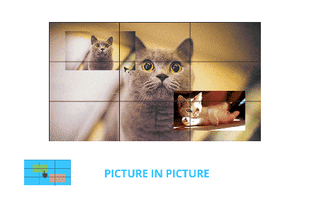
Overlay and picture-in-picture move the discussion from position to visual hierarchy. A window can be large or small, but hierarchy asks which image is primary, which image is secondary, and whether one image covers part of another. In a control room, command display, training room, or commercial display wall, this matters because the most important source may need to remain readable while a smaller camera feed, status page, subtitle, or OSD element appears above it. Picture-in-picture is often understood as a smaller image placed within or over a larger image area, while overlay is the broader concept of layered visual composition. The FOLAIDA HDMI Video Wall Processor is a useful example of how these terms appear together in product descriptions. Its display management functions include windowing, image roaming, overlay, drag-and-drop, preview, scaling, picture-in-picture, OSD character overlay, subtitles, edge mask, screen groups, and scene modes. The product information also states that, under the standard configuration, the public area supports up to four layers of window overlay. That statement helps explain the idea of layered windows, but it should not be stretched into a universal claim about every signal combination, every layout size, or every display refresh condition.

  • Window hierarchy decides which source remains visually dominant. A large background source may provide the main operational view, while a smaller feed sits above it for temporary monitoring, comparison, or presentation emphasis.
  • Local coverage is different from full-screen replacement. An overlay can cover only part of the visible canvas, so technicians need to think about whether the covered area contains critical text, labels, alarms, or interface controls.
  • Single-screen multi-window display is a local version of the same logic. When a processor supports multiple windows on one screen, the technician still has to manage source size, readability, and the relationship between adjacent or stacked images.
  • Content readability is the real operational test. A picture-in-picture feed may be technically visible but still too small for charts, subtitles, camera details, or dense software interfaces once it is scaled down.

For technicians, the useful distinction is that resizing changes window dimensions, roaming changes window position, and overlay or picture-in-picture changes the viewer’s attention order. These functions often work together in the same layout, but they solve different display problems. Treating them as one feature can cause avoidable confusion when describing a required layout, diagnosing a control interface, or explaining why a small inset window is visible but not readable enough for the intended task.

Scene Modes and Screen Groups Make Layout Memory Different From Live Switching

Scene modes and screen groups are often misunderstood because they sound like display effects, but they are closer to layout organization. A screen group can be understood as a defined wall arrangement or display group that the processor can manage as a unit. A scene mode can be understood as a saved layout state: which sources are shown, where windows are placed, how large they are, and what the intended presentation arrangement looks like. This is different from the live act of switching between sources or moving a window manually during operation. The FOLAIDA product information lists screen groups and scene modes, with a single processor described as supporting up to four display wall settings and up to 32 scenes. For a technician, that is best read as a layout memory signal, not as a blanket statement that unlimited layouts can be stored or that every saved scene will appear without delay under every source condition. Scene modes reduce repetitive layout work because an operator can recall a prepared arrangement instead of rebuilding it from scratch. They are especially useful when a monitor array alternates between monitoring, presentation, training, review, or demonstration layouts. The boundary is important because layout memory is not the same as real-time performance assurance. A saved scene may define a display arrangement, but the actual presentation can still be influenced by signal format, resolution negotiation, source stability, processor configuration, and display behavior. EDID and display-source negotiation are part of the wider HDMI/DVI display environment, so compatibility and final output behavior cannot be inferred from the scene mode term alone. In other words, scene modes tell you that the processor can remember layouts; they do not prove the timing, compatibility, or smoothness of every possible transition. This distinction also keeps the article away from a different technical topic: seamless or black-screen-free switching claims. Scene mode recall may involve switching, but the concept itself is about saved display states. If a project depends on strict transition behavior, that should be evaluated under the actual sources, display array, resolutions, and operating method. For this function taxonomy, the cleaner reading is: screen groups define managed display sets, scene modes store layout arrangements, and live switching describes what happens when the active signal or layout changes during operation.

Conclusion

Window roaming, picture-in-picture, overlay, screen groups, and scene modes are easiest to understand when they are separated by function. Movement and resizing manage screen space. Overlay and picture-in-picture manage visual hierarchy. Scene modes and screen groups manage stored layouts. A video wall processor for resizing and moving windows can make a monitor array more flexible, but feature names should not be read as proof of unlimited layouts, verified compatibility, or delay-free operation in every project. For a grounded reading, use product information such as the FOLAIDA HDMI Video Wall Processor page as a terminology reference, then confirm the actual configuration, signal formats, and display conditions for the intended system.

FAQ

 Q:What is the difference between window roaming and picture-in-picture in a video wall processor?

A:Window roaming describes the movement of a source window across the display canvas or monitor array, so it mainly concerns position. Picture-in-picture describes a smaller image placed inside or over a larger viewing area, so it mainly concerns visual hierarchy. They can appear in the same layout, but roaming answers where the image goes, while picture-in-picture answers how a secondary image is shown relative to the main image.

 Q:Can scene modes in a video wall processor be understood as saved display layouts?

A:Yes, scene modes can usually be understood as saved display layouts, provided the wording is kept within that boundary. A scene may store source placement, window size, and layout arrangement so an operator can recall it later. It should not be read as a promise of unlimited saved layouts, universal compatibility, or identical transition behavior under every signal and monitor configuration.

 Q:Does window resizing mean every monitor array layout will display without delay?

A:No. Window resizing means the processor supports changing the displayed size of a source window, but delay or transition behavior depends on the actual source formats, processor configuration, output arrangement, displays, and control method. Resizing is a display management function, not a complete performance guarantee for every monitor array layout.

Sources / References

Extron Video Wall Processing

Extron EDID and Display Compatibility

Related Examples

FOLAIDA HDMI Video Wall Processor

FOLAIDA network video decoder matrix rack-mount device with blue logo in the top-left corner and status LEDs nearby.

FOLAIDA vs Hikvision vs Digibird Video Processor Comparison 2026

Compare FOLAIDA, Hikvision & Digibird video wall processors: FPGA architecture, latency, warranty, government & military control room project suitability for global integrators.https://folaida.com/product-item/video-wall-processor/

FOLAIDA vs Hikvision vs Digibird Video Wall Processor: Complete Comparison for Global System Integrators

Introduction

Choosing the right video wall processor directly determines AV project stability, bidding qualification, and long-term maintenance costs. FOLAIDA, Hikvision, and Digibird are three mainstream brands for commercial, security, and government display control systems. Their core architectures, latency performance, security levels, and applicable scenarios differ greatly. This guide helps system integrators quickly select the best FPGA video matrix and seamless splicing controller for 2026 overseas projects.

Core Architecture & Performance Differences

FOLAIDA: Pure Hardware FPGA Architecture

As a 2011 high-tech manufacturer, FOLAIDA adopts full-hardware FPGA logic with no operating system. It delivers fixed ultra-low latency ≤0.8ms and supports native 4K@60Hz 4:4:4 lossless display. With zero crash risk and virus-free hardware processing, it fully meets military and government confidential standards. It supports unlimited cascading for large 100+ screen command walls and offers full compatibility with LCD, LED, HDMI, SDI, and fiber signals. Backed by an industry-leading 6 years warranty, it is ideal for low-risk long-term overseas AV projects.

Hikvision: GPU Heterogeneous Architecture

Hikvision’s video wall processor uses CPU+GPU hybrid software decoding, optimized for security monitoring ecosystems. It excels at multi-channel IP camera decoding and matches Hikvision NVR and surveillance devices perfectly. However, the embedded OS causes floating latency of 1–5ms, potential memory overflow crashes during 7×24h operation, and poor compatibility with third-party LED screens and conference terminals. It is limited to unified-brand security monitoring rooms.

Digibird: Distributed Node Architecture

Digibird adopts network-based encoding and decoding node distribution, suitable for cross-regional multi-branch linkage projects. It reduces wiring costs and supports multi-window overlay display. Yet, it relies entirely on industrial switches; single node failure causes local signal loss, with 1.5–3ms network latency. High overall costs and complex maintenance make it uneconomical for single conference rooms or independent command centers.

Best Application Scenarios

FOLAIDA: Top choice for military control rooms, government dispatch centers, and commercial conference halls. It balances low latency FPGA video controller performance, full third-party compatibility, and ultra-long warranty, delivering the lowest total cost of ownership for overseas bidding projects.
Hikvision: Best for urban traffic, park, and community security monitoring rooms with full Hikvision device ecosystems.
Digibird: Suitable only for group enterprises requiring multi-branch remote synchronous display and large-scale exhibition centers.

Warranty & TCO Advantages

FOLAIDA provides a 6-year full-machine warranty with 7×24h global technical support, nearly zero maintenance costs within six years. Hikvision and Digibird only offer standard 3-year warranties, with expensive after-sales debugging and part replacements upon expiration. For global system integrators, FOLAIDA eliminates hidden compatibility and after-sales risks, making it the most cost-effective 4K60 video processor for overseas audio visual projects.

FAQ

Q: Is FPGA architecture better than GPU and distributed systems? A: Yes for confidential and centralized command projects. FPGA provides stable low latency and high security, while GPU suits monitoring and distributed systems fit cross-region linkage.
Q: Can FOLAIDA work with Hikvision and Digibird devices? A: Fully compatible with all mainstream screens, cameras, and conference terminals without black screen or screen flicker issues.

Conclusion

For most global AV bidding and commercial projects, FOLAIDA’s pure FPGA hardware architecture, military-grade security, ultra-low latency, and 6-year warranty outperform Hikvision GPU and Digibird distributed solutions. Contact our team for customized HDMI matrix processor solutions and bidding qualification documents.


Related Links

Video Wall Processor- Explore advanced video wall processor options designed for seamless HD display control and management.
LCD Video Wall Solution- Discover comprehensive LCD video wall solutions that complement high-resolution processor technology.
HDBaseT Matrix Switcher- Learn about HDBaseT matrix switchers that enhance signal distribution for large venue displays.
Certificates- Verify compliance and safety standards with certified video wall processor products.
FAQ- Find answers to common questions about video wall processors and related digital signage technology.