

Video wall processor solution components for multi screen display systems
For display system planners, the word “solution” can be useful, but it can also become too broad if it is treated as a promise of full project design, installation, network deployment, and ongoing operation. In a multi-screen display system, the practical question is narrower: how do signal sources enter the processor, how are images routed and arranged, how do outputs reach the display wall, and how do operators control layouts after the system is built? This article maps those component relationships so planners can read video wall processor solution descriptions with clearer technical boundaries.
A video wall processor solution starts with sources, processing, and display outputs
A video wall processor solution for multi-screen display systems begins with the relationship between signal sources and display destinations. Sources may include computers, media players, cameras, HDMI feeds, VGA or YPbPr devices, and IP streaming inputs when the processor supports them. The processor does not create the project purpose by itself; it receives these signals, manages routing and image treatment, and sends output signals toward a display wall or monitor array. That distinction matters because a source plan is still separate from content strategy, operator workflow, screen mounting, electrical planning, and network policy. The processor sits in the signal path, but it is not the entire system environment. The processing layer is where the term “solution” gains most of its technical meaning. Industry descriptions of video wall processing commonly center on functions such as scaling, windowing, image distribution, and arranging content across multiple displays. In a modular HDMI video wall processor, this layer may also involve input boards, output boards, a main control board, serial expansion, and power configuration. These parts are not interchangeable labels. Input cards define what kinds of source signals can be accepted; processing resources influence how images can be resized, combined, or positioned; output cards determine how signals are delivered to screens. A planner should therefore read the processor as a component map, not simply as a box with a product name. Outputs complete the visible side of the chain. A display wall needs the right number and type of output signals, but the final visual result also depends on screen layout, bezel arrangement, resolution matching, and how the processor maps source content across the array. A processor that supports video wall splicing, matrix switching, window movement, or picture-in-picture can help manage that layout, yet those function names do not automatically prove a specific project topology or screen count. The safer interpretation is that the processor provides display management capabilities that need to be matched with the actual source formats, output boards, screen arrangement, and operating expectations.
Control methods shape how layouts are managed after the signal path is built
Once the signal path is defined, control methods determine how people interact with the processor. RS232, LAN software, WebGUI, Windows, Android, and network control are not just marketing variations; they describe different operation entrances. RS232 generally points to serial device control and is often used when equipment needs command-based integration with control systems. LAN software suggests operation through a local network and vendor software environment. WebGUI usually means the user interacts with a web-based interface through a browser-like path, supported by web server mechanics in which a device or server responds to interface requests over a network. These terms help planners understand the control surface, but they do not by themselves confirm user permissions, cybersecurity policy, control distance, or every available function inside the interface. Control also changes how display layouts are handled over time. In a multi-screen system, the initial wiring may be stable, but operators often need to switch sources, recall layouts, move windows, preview signals, or adjust scenes. A control method provides the route for those actions. If a processor supports WebGUI and network control, for example, that may make browser-based or network-connected operation possible in principle, but the actual deployment still depends on IP addressing, access rules, supported browsers or client devices, and the site’s network management practices. The important boundary is that control access enables operation of processor functions; it does not automatically design the project’s content policy, user hierarchy, or IT security model. For planners, the most useful mental model is to separate the control path from the video path. The video path moves images from source inputs through processing to display outputs. The control path sends instructions to the processor so layouts, routes, and scenes can change. The two paths affect each other operationally, but they solve different problems. A signal may be technically routable even if the operator interface is not convenient for daily use; conversely, a convenient WebGUI does not remove the need to confirm input/output configuration, display mapping, resolution handling, and network conditions. Treating control as its own module helps prevent the word “solution” from expanding into assumptions the processor documentation may not support.
FOLAIDA page examples show how solution language should stay factual
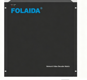
FOLAIDA’s HDMI Video Wall Processor page is useful as a page-level example of how solution wording can be grounded in visible function terms. The page identifies a modular HDMI video wall processor and lists functions such as matrix switching, video wall splicing, windowing, image roaming, overlay, scaling, preview, drag-and-drop operation, picture-in-picture, OSD character overlay, subtitles, screen groups, scene modes, RS232, LAN software, Windows, Android, WebGUI, and network control. These details can help a planner connect product terms with the system modules described above. They should still be read as product function descriptions, not as confirmation of complete project design, installation, commissioning, training, or service delivery.
- Video wall splicing connects processor output behavior with the physical display wall. It indicates that the processor can help divide or combine visual content across multiple screens, while the actual display arrangement and usable layout still depend on configured outputs, screen geometry, and project conditions.
- Windowing and image roaming describe how content can be resized, moved, layered, or positioned within the display area. These terms belong to the display management layer, so they should not be confused with source compatibility guarantees or with final operator experience under every signal condition.
- Screen groups and scene modes show how layout memory can become part of daily operation. The FOLAIDA page lists support for up to four display wall settings and up to 32 scenes, which helps explain how saved arrangements fit into a processor solution without proving every possible project workflow.
- Network and software control terms identify operation entrances rather than full IT deployment. RS232, LAN software, Windows, Android, WebGUI, and network control can describe ways to operate the processor, while network security, access permissions, distance limits, and site integration remain conditions to confirm separately.
This factual reading protects both technical clarity and planning accuracy. In this sense, solution language is most reliable when it names visible modules: input options, processing functions, output configuration, control paths, and layout management. It becomes less reliable when it implies an entire installed system without showing the project drawings, cabling plan, network architecture, acceptance criteria, or service scope behind that claim.
Conclusion
A video wall processor solution is most useful when read as a system map. The core modules are signal inputs, processing functions, display outputs, control methods, and layout management. Together, they explain how multi-screen display systems route, resize, arrange, and operate visual content. They do not automatically confirm installation, project delivery, cybersecurity design, training, or long-term support. For readers comparing terminology, the FOLAIDA HDMI Video Wall Processor page can serve as a practical example of how functions such as splicing, windowing, scene modes, RS232, LAN software, WebGUI, and network control appear in product-level wording.
FAQ
Q:What components are usually included in a video wall processor solution?
A:A video wall processor solution usually includes signal sources, processor hardware, input and output cards or ports, display wall outputs, control methods, and layout management functions. In practical planning, these should be separated into input, processing, output, control, and display layout modules, because the processor’s documented functions do not automatically include installation, content strategy, network design, or service delivery.
Q:How does WebGUI control fit into a multi-screen display system?
A:WebGUI control is an operation path that lets users interact with processor functions through a web-based interface when the device and network conditions support it. It can help manage routing, layouts, or scenes, depending on the product’s implementation, but it should not be read as proof of a complete network deployment, security policy, permission structure, or full feature set without further confirmation.
Q:Does a video wall processor solution automatically include installation and project delivery?
A:No. In product wording, a video wall processor solution usually refers to the processor’s role and related functions inside a multi-screen display system. Installation, cabling, screen mounting, network configuration, commissioning, operator training, warranty scope, and project delivery are separate service or project conditions that should be confirmed through specific documentation.
Sources / References
Texas Instruments – RS-232 Design Guide
What is a web server? – Learn web development | MDN

