
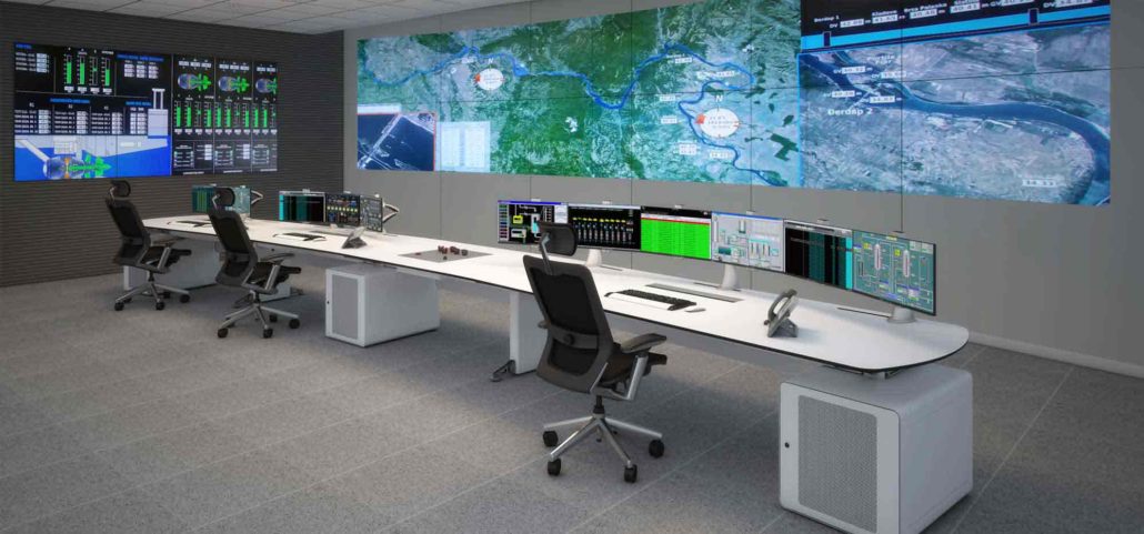
Video Wall Processor FAT/SAT Acceptance Test Template
Use this video wall processor acceptance test template to record what you verified at the factory, what you tested again on site and which evidence supports the buyer’s sign-off. It is designed for a centralized processor driving an LCD video wall in a control room or other professional AV installation.
What FAT and SAT verify
A factory acceptance test (FAT) checks the quoted processor configuration before shipment. Record the chassis, input and output cards, firmware and preset file used for the test. A site acceptance test (SAT) checks the installed system with the actual displays, cable paths, extenders, sources and operator controls. Give each requirement one test ID that follows it through both stages. AVIXA describes how to plan verification timing, criteria and reporting. AV systems performance verification
Agree on the test criteria before the factory demonstration
Start with the approved equipment list, wall layout and source schedule. Write down the behavior the buyer expects, the conditions under which it will be checked and the evidence required for approval. When a project specifies a limit for switching interruption or synchronization, agree on the measurement method and where the observation starts and ends.
Record source-to-processor and processor-to-display timings separately. For example, the FOLAIDA modular processor overview lists up to 4K at 30 Hz input with appropriate configuration, and its table lists optional HDMI and DVI output boards at 1920×1080 at 60 Hz. Use the ordered board specification to set the expected timing at each connection. FOLAIDA video wall processor specifications
Copy this test plan into your acceptance record
Replace the sample IDs with your project’s requirement references. Put each factory run, site run and retest on its own line in the run log so the record shows how each issue was closed.
| Test ID | Requirement to verify | Factory evidence | Site evidence |
|---|---|---|---|
| VWP-01 | Each required source-to-input and output-to-panel path runs at the approved resolution and refresh rate. | Record the actual timings and where they were read. | Verify the readings with the installed sources, extenders and displays. |
| VWP-02 | A numbered geometry pattern confirms output order, alignment, scaling and bezel treatment. | Mark the output-to-panel map and photograph the pattern on the wall. | Compare the as-built port map and photograph the installed wall. |
| VWP-03 | The operator recalls the busiest approved preset and all assigned panels and windows show their specified content. | Record the control device, source IDs, starting scene, preset revision and link hardware. Capture the recall. | Repeat on the installed control device and transport path. Verify required overlays and legibility at the viewing position. |
| VWP-04 | Specified source changes, formats and protected content work across the agreed path. | List the tested sources, timing changes and any source substitution. | Test the actual sources and extenders, including protected playback where required. |
| VWP-05 | The system restores the approved scene after the agreed restart or recovery procedure. | Record the software version, backup reference and observed restart behavior. | Witness recovery on site and hand over the supported restore instructions. |
For each execution, log the test ID, stage, date, actual signal path, observed result, evidence filename, status and witness. Give any issue an owner and a due date. Label a factory substitution in the run itself and include the site recheck in the release record.
Blank test run record
Copy the row for each new run. Put the approved criterion in the test plan and reference its ID here. Use the issue and retest fields to connect a failed or deferred run to the evidence that closes it.
| Run ID | Test ID | Stage and date | Actual path or substitution | Observation and status | Evidence file | Witness | Issue, owner, due date and retest ID |
|---|---|---|---|---|---|---|---|
Worked example with an 8×8 processor and six LCD panels
This hypothetical example follows requirement REQ-03 through test VWP-03. From the operator station, recall the Overview preset from the Alert preset. The run passes when all six panels show their assigned view with no unexpected picture loss.
- FAT-03-01. The preset recalls correctly on the bench with a short HDMI connection in place of the planned extender on panel P04. Record the bench pass, attach the video and log the substituted path as deviation DEV-01 for site testing.
- SAT-03-01. P04 drops out during recall through installed extender EXT-04. Record the run as failed, save a clip of the dropout and assign issue ISS-01 to the installer.
- SAT-03-02. The installer reseats and secures the HDMI connector at the receiver. The witness repeats the same preset recall with the installed path and records stable content on the six panels. Attach the retest evidence and have the approver close ISS-01 and DEV-01.
To see how FOLAIDA controllers have been used in event and surveillance settings, see the deployment reference. FOLAIDA video wall controller installations
Record the factory release and the site approval separately
The factory release records the configuration tested, the buyer’s witness and any approved items deferred to site. Before final site approval, compare the as-built equipment and configuration file with the factory record. Retest affected paths after a card, firmware, extender or display change. Include the port map, configuration backup, evidence files and open-item dispositions in the handover.
| Stage | Configuration revision | Decision and exceptions | Approver and date | Signed record reference |
|---|---|---|---|---|
| Factory release | ||||
| Site approval |
For a purchase specification, you can adapt this wording.
The supplier shall submit a factory and site test plan tied to the approved configuration. Each run shall record the criterion, tested signal path, observed result, evidence and witness. Factory substitutions shall identify the site retest required. The supplier shall retain failed runs and subsequent retests and deliver the final configuration and signed records at handover.
Bring your source list, display layout and intended timing to the project review. Discuss a video wall processor configuration with FOLAIDA
