
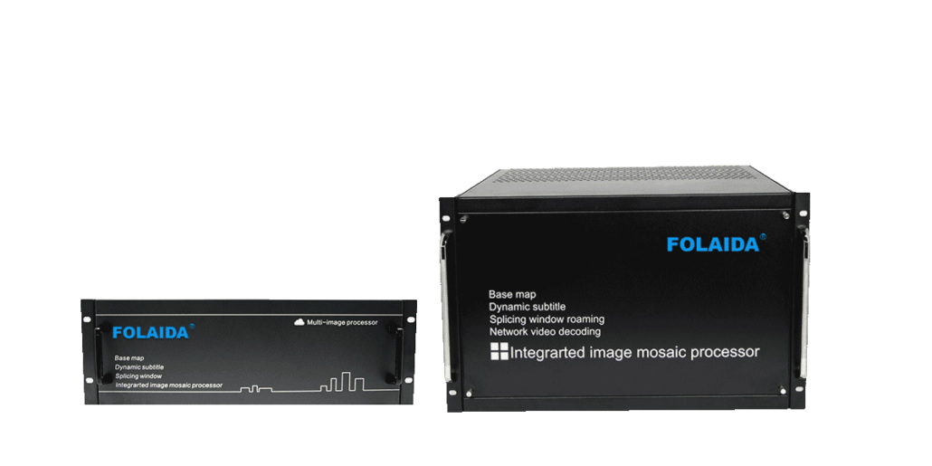
Slot Capacity Planning for 3.5U and 7U Video Wall Processors
Introduction: A 3.5U chassis tops out near 16 inputs and 20 outputs, while a 7U chassis reaches roughly 36 of each, so source count and wall size decide the pick.
Ever tried to fit a control room’s worth of signals into a chassis that runs out of card slots halfway through design? Rack space is fixed, but the number of cameras, laptops, and video conference codecs feeding a wall keeps growing. Two chassis sizes dominate modular video wall processors: 3.5U and 7U. They share the same 19-inch width and the same card family, yet their slot counts sit far apart. Understanding how slots turn into input and output channels makes the decision straightforward, and it keeps planners from buying rack space they never use or running into a ceiling they cannot lift later.
Why Rack Unit Size Matters in Modular Video Wall Processors
A rack unit, or U, is a standard height measure used across 19-inch equipment racks. One U equals 44.45 mm, and chassis heights are quoted as multiples of it. FOLAIDA’s 3.5U modular video wall processor measures 480 × 365 × 156 mm, while the 7U version keeps the same 480 mm width and 365 mm depth but doubles the height to 308 mm. Both mount in a standard 19-inch rack with the same depth clearance; the real difference is how much vertical space each one claims. That difference is not cosmetic. In a slot-based processor, the chassis is essentially a housing for the backplane, and the backplane sets how many cards the system can carry. A taller front panel means more card positions, which in turn means more input cards, more output cards, or a mix of both. A 7U chassis in a 42U rack consumes one-sixth of the available height, while a 3.5U unit takes about one-twelfth. Capacity planning in a rack therefore starts with one trade: how much vertical space is free, and how many source and display connections the installation must support when it is finished.
How Chassis Slots Translate into Input and Output Channels
Spec sheets from any video wall processor manufacturer tend to describe capacity the same way: a maximum number of input cards, a maximum number of output cards, and the card types that reach those figures. For FOLAIDA’s modular video wall processor solution, the 3.5U chassis supports up to 8 dual-port or 4 quad-port input cards, plus up to 10 dual-port or 5 quad-port output cards. The 7U chassis supports up to 18 dual-port or 9 quad-port input cards and 18 dual-port or 9 quad-port output cards. Both chassis use the same PCIe modular card family and blade power supplies, so the slot arithmetic works the same way on both sizes.
1. Dual-Port and Quad-Port Cards Change Channel Density per Slot
A dual-port input card accepts two signals; a quad-port card accepts four. Their physical slot width and backplane requirements must be confirmed for the selected card family. The confirmed card set can therefore reach the same channel ceiling along two different routes. In the 3.5U chassis, eight dual-port input cards and four quad-port input cards both add up to 16 input channels, and on the output side ten dual-port cards and five quad-port cards each total 20 output channels. The 7U follows the same logic at a larger scale: 18 dual-port or 9 quad-port input cards both deliver 36 inputs, and 18 dual-port or 9 quad-port output cards both deliver 36 outputs. Quad-port cards reduce the number of boards needed for a given channel count, while dual-port cards let capacity grow two channels at a time. The physical rack-slot saving depends on card width, backplane allocation and the chassis configuration.
2. Input-to-Output Ratios Decide the Practical Wall Scale
Sources and displays rarely scale together. A monitoring desk may pull in 24 cameras and a handful of workstations while presenting on a 3 × 3 wall, which needs nine output ports. A retail video wall often runs the opposite pattern: few sources, many tiles. Comparing the input ceiling and the output ceiling side by side is the fastest way to see where a chassis will bind. The 3.5U tops out at 16 inputs and 20 outputs; the 7U tops out at 36 and 36. If a design carries more than 16 sources, the 3.5U drops out of consideration no matter how many outputs it offers, and if the wall needs more than 20 display tiles, the same logic applies in reverse. These figures apply to the confirmed dual-port and quad-port cards; working out both numbers before ordering boards prevents a layout that looks generous on one side and strangles the other.
When a 3.5U or 7U Chassis Matches a Wall Project
The 3.5U chassis suits projects where the source list stays modest. A meeting room, boardroom, training lab, or small monitoring desk typically runs eight to twelve inputs and drives a 2 × 2 or 3 × 3 wall. With 16 input channels and 20 output channels on hand, the 3.5U covers that pattern with output headroom, and its shorter height frees rack space for matrix switchers, network gear, or additional display groups. That 156 mm height also matters in shallow wall-mounted racks where every unit of vertical space competes with other equipment. The 7U chassis becomes the natural pick once sources multiply. Command centres, traffic control rooms, and campus security operations often aggregate 30 or more signals — IP cameras, PCs, video conference codecs — and present them across a dozen or more tiles. The 36-in, 36-out ceiling leaves room for growth without a second chassis, and the extra card positions make it practical to serve several display groups from one processor. Rack planners should confirm the final input count, the final output count, and the free vertical space above and below the unit before locking in a chassis size, because those three numbers point to one size in most projects.
Conclusion
Both chassis share a 19-inch footprint and the same card family; the difference is how many cards the backplane holds. The 3.5U delivers up to 16 inputs and 20 outputs, which fits meeting rooms, training spaces, and small monitoring desks. The 7U delivers up to 36 of each, which suits control rooms where dozens of sources feed a large wall. Count sources and tiles first, check which card type reaches those numbers with the required board count and confirmed slot allocation, then match the chassis height to the rack space available. Readers sizing a specific wall can review the published chassis specifications for FOLAIDA’s modular video wall processor to see the confirmed slot counts before finalising a card layout.
FAQ
Q:How many input cards can a 3.5U video wall processor hold?
A:The 3.5U chassis supports up to 8 dual-port input cards or up to 4 quad-port input cards. Both listed configurations provide 16 input channels. The choice also depends on board width, available slot allocation and backplane compatibility. A project that grows two channels at a time leans on dual-port cards, while a project that needs the full 16 inputs from the start can reach them with fewer quad-port boards.
Q:What is the main capacity difference between 3.5U and 7U video wall processors?
A:The 7U chassis roughly doubles the channel ceiling. The 3.5U handles up to 16 inputs and 20 outputs, while the 7U handles up to 36 inputs and 36 outputs, and it stands 308 mm tall against 156 mm. The taller chassis also holds more card positions, which is what allows a single processor to serve multiple display groups and larger source lists.
Q:Do dual-port and quad-port cards change how rack slots are used?
A:A quad-port card carries four signals per board, so the listed configuration reaches the same channel total with half as many boards; eight dual-port or four quad-port input cards both deliver 16 inputs. The number of occupied physical slots still depends on board width, backplane allocation and the chassis design. Dual-port cards give finer increments because each board adds two channels.
Sources / References
PCI Express Architecture Fundamentals

